Eureka AIR delivers breakthrough ideas for toughest innovation challenges, trusted by R&D personnel around the world.

Method and arrangement for deeply resolved optical detection of a sample

a deep resolution, optical detection technology, applied in the field of fluorescence microscopy, can solve the problems of limited usable sequential recording of images, readout and calculation, etc., and achieve the effect of preventing the limitation of the dynamic range of the detector and preventing residual modulations of the confocal section imag

Inactive Publication Date: 2007-01-30
CARL ZEISS MICROSCOPY GMBH
View PDF11 Cites 7 Cited by
  • Summary
  • Abstract
  • Description
  • Claims
  • Application Information

AI Technical Summary

Benefits of technology

[0024]By means of the arrangements according to the invention, it is possible to generate the optical section images already at the detector. This prevents limiting of the dynamic range of the detector due to nonconfocal background signals. A sequential recording and readout of the phase images for calculating in the PC is no longer necessary, so that the speed of the detector is entirely available for the recording of confocal section images. Residual modulations in the confocal section image are prevented.

Problems solved by technology

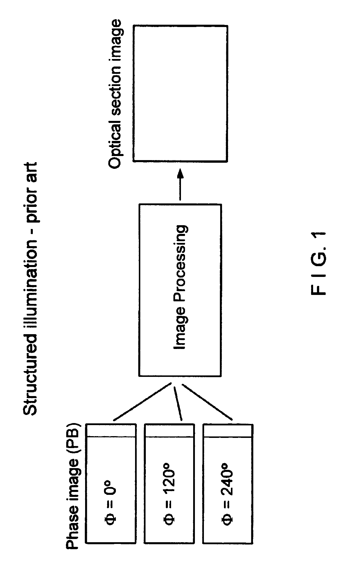
A disadvantage in the prior art consists in that a plurality of images must be sequentially recorded, read out and calculated.
Further, the usable dynamic range of the detector is limited depending on the strength of the nonconfocal background signal of the specimen (i.e., signals outside of the focal plane).

Method used


Image

  • Method and arrangement for deeply resolved optical detection of a sample
  • Method and arrangement for deeply resolved optical detection of a sample
  • Method and arrangement for deeply resolved optical detection of a sample

Examples


Embodiment Construction

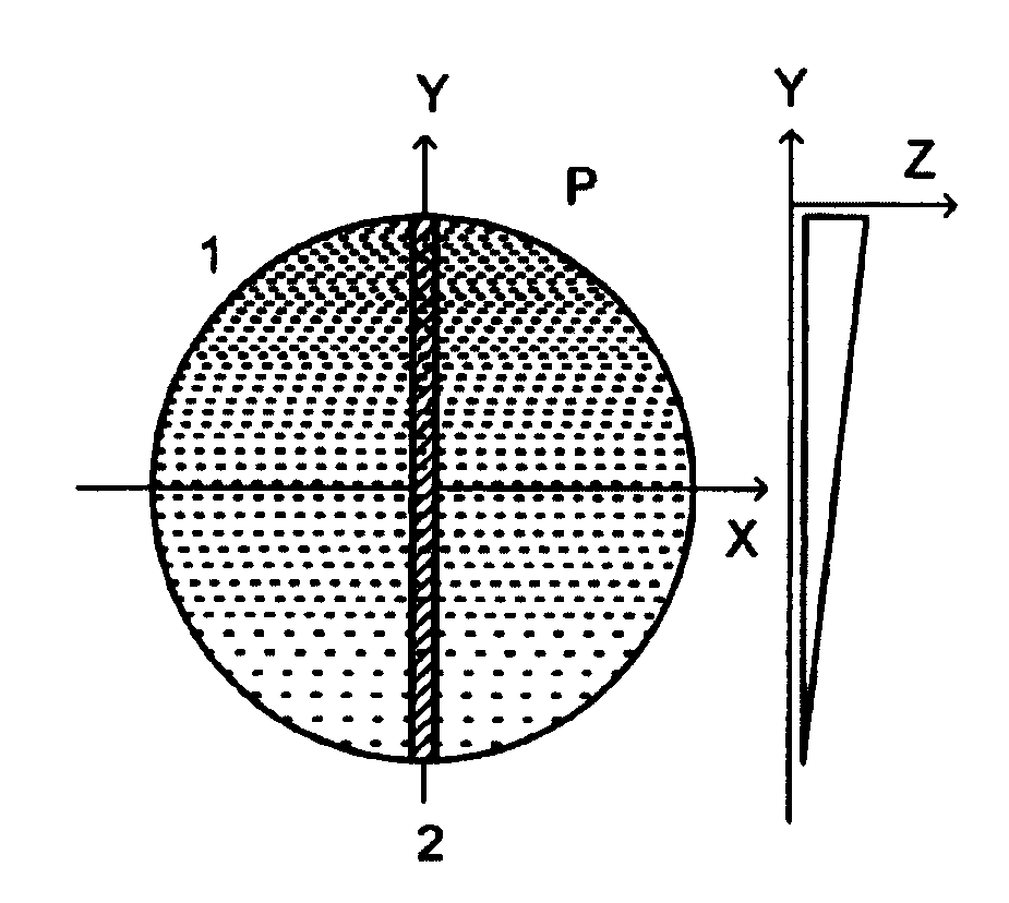
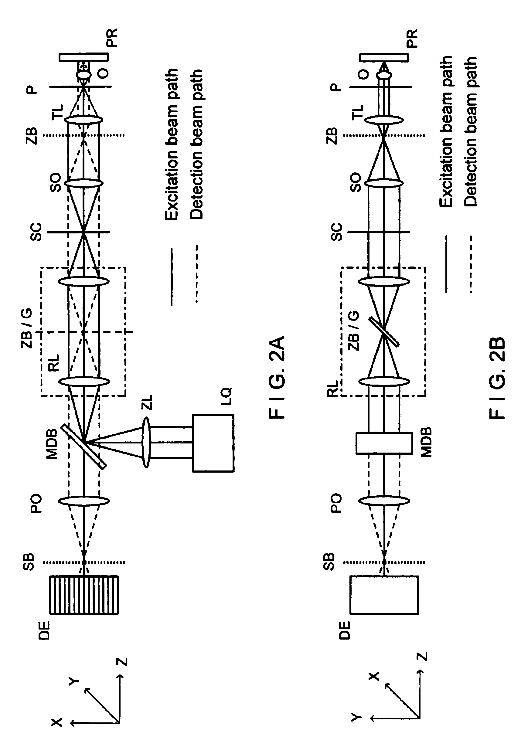
[0037]The arrangement, according to the invention, for a line scanner is shown schematically in FIG. 2A (side view) and FIG. 2B (top view). The solid lines in the beam path represent the illumination beam path. The dashed lines represent the detection beam path. In a line scanner, the specimen is illuminated by a line focus, e.g., along the X coordinate which is shifted in the coordinate vertical to the line. For this purpose, the light source LQ (FIG. 2A), which can radiate one wavelength or a plurality of wavelengths as well as wavelength bands or which can be a white light source, is focused in a line-shaped manner in an intermediate image plane ZB of the microscope device by means of optics ZL, cylindrical lens, and optics RL, relay lens. A diffraction-limited, line-shaped intensity distribution results along the X coordinate on the specimen PR by focusing in Y-direction in the second intermediate image ZB / G, where G is an amplitude grating, after traversing the scanner SC, scan...


PUM


Abstract

A method and arrangement for the depth-resolved optical detection of a specimen with an illumination light distribution of at least one wavelength generated on or in a specimen and detection particularly of the light that is influenced due to interaction with the specimen, particularly fluorescent light and / or reflected light and / or luminescent light and / or scattered and / or transmitted light, wherein the illumination light has a modulation in at least one spatial direction and the detection light which is modulated like the illumination light is spatially split into two components having a phase shift relative to one another, the components are measured separately and an optical section image of the specimen and / or of part of the specimen is calculated from them.

Description

CROSS-REFERENCE TO RELATED APPLICATION[0001]This application claims priority of German Application No. 102 54 139, filed Nov. 15, 2002, the complete disclosure of which is hereby incorporated by reference.BACKGROUND OF THE INVENTION[0002]a) Field of the Invention[0003]The invention is directed to a method and an arrangement in microscopy, particularly fluorescence microscopy, for examining predominantly biological specimens, preparations and associated components. This includes methods for screening active ingredients (high throughput screening) based on fluorescence detection. Simultaneous examinations of fluorescence specimens in real time by means of simultaneous illumination of the specimen in a plurality of points on the specimen are possible.[0004]b) Description of the Related Art[0005]A typical area of application of light microscopy for examining biological preparations is fluorescence microscopy (Pawley, “Handbook of Biological Confocal Microscopy”, Plenum Press 1995). In t...

Claims


Application Information

Patent Timeline
IPC IPC(8): G02B5/04G02B27/12G01N21/64G02B21/00G06T5/50G06T7/00
CPCG01N21/6428G01N21/6458G06T7/0022G02B21/0032G02B21/006G06T5/50G01N2021/6417G01N2021/6478G06T7/97
Inventor WOLLESCHENSKY, RALF
Owner CARL ZEISS MICROSCOPY GMBH
Why Eureka
Eureka Blog
Learn More