System and method for identifying defects in a composite structure

Active Publication Date: 2007-01-30
THE BOEING CO
View PDF34 Cites 61 Cited by
  • Summary
  • Abstract
  • Description
  • Claims
  • Application Information

AI Technical Summary

Benefits of technology

[0014]Thus, the present invention provides a system and method for identifying defects in a composite structure by providing an obliquely-mounted light source having an infrared component such that defects in the composite structure will be more readily detectable. As a result, the system and method permit the

Problems solved by technology

However, the fabrication process has been disadvantageously slowed by the inspection process.
However, this system provides only a single reference point when inspecting workpieces that cannot be modified by the operator.
However, this system also requires that the standard measurements are preloaded into the computer and not controllable by the operator thereafter.
However, each of these systems is susceptible to obtaining false readings due to glare or other problems caused by ambient lighting or by the laser-based scanning system.
In this r

Method used


Image

  • System and method for identifying defects in a composite structure
  • System and method for identifying defects in a composite structure
  • System and method for identifying defects in a composite structure

Examples


Embodiment Construction

[0022]The present invention now will be described more fully hereinafter with reference to the accompanying drawings, in which preferred embodiments of the invention are shown. This invention may, however, be embodied in many different forms and should not be construed as limited to the embodiments set forth herein; rather, these embodiments are provided so that this disclosure will be thorough and complete, and will fully convey the scope of the invention to those skilled in the art. Like numbers refer to like elements throughout.

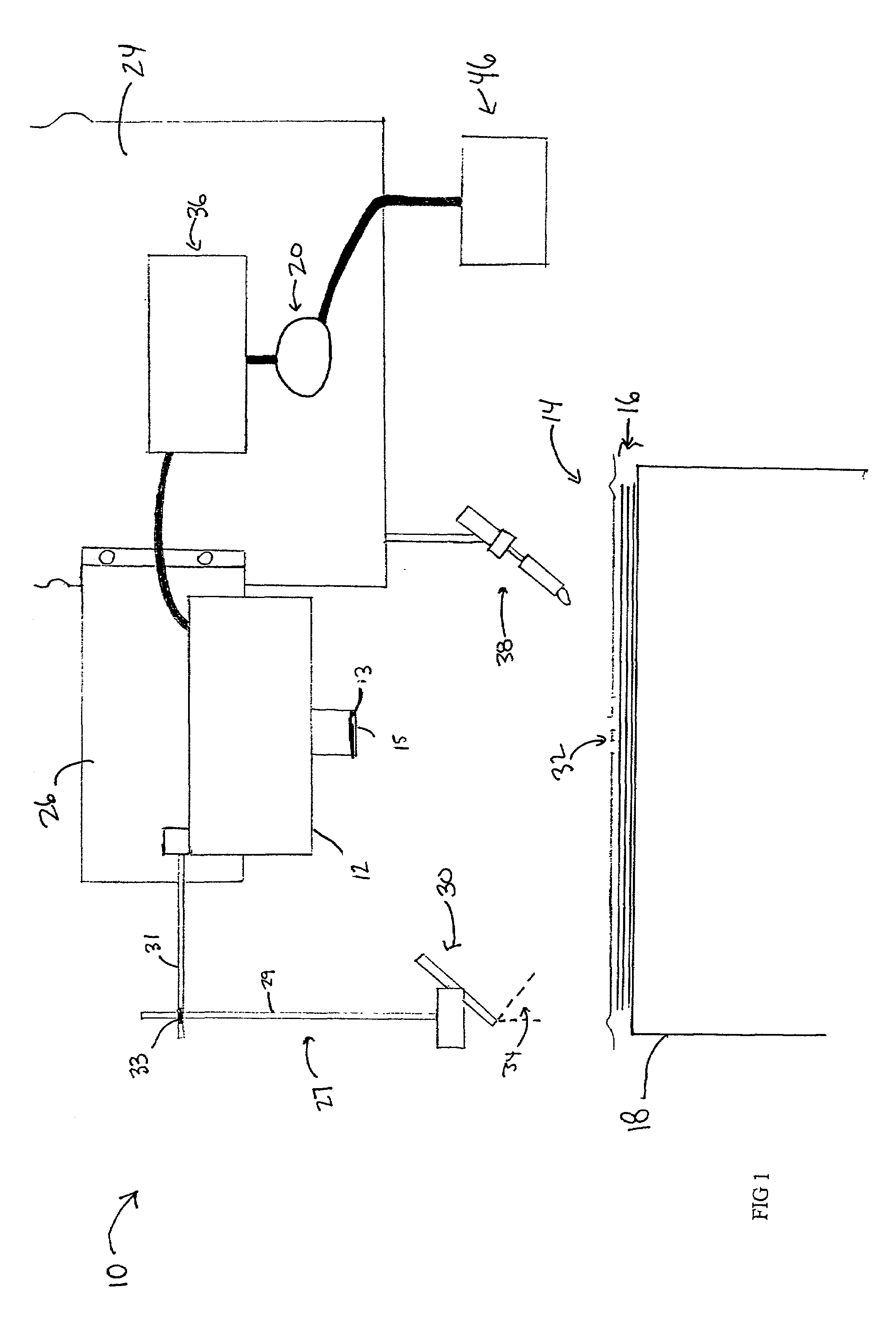
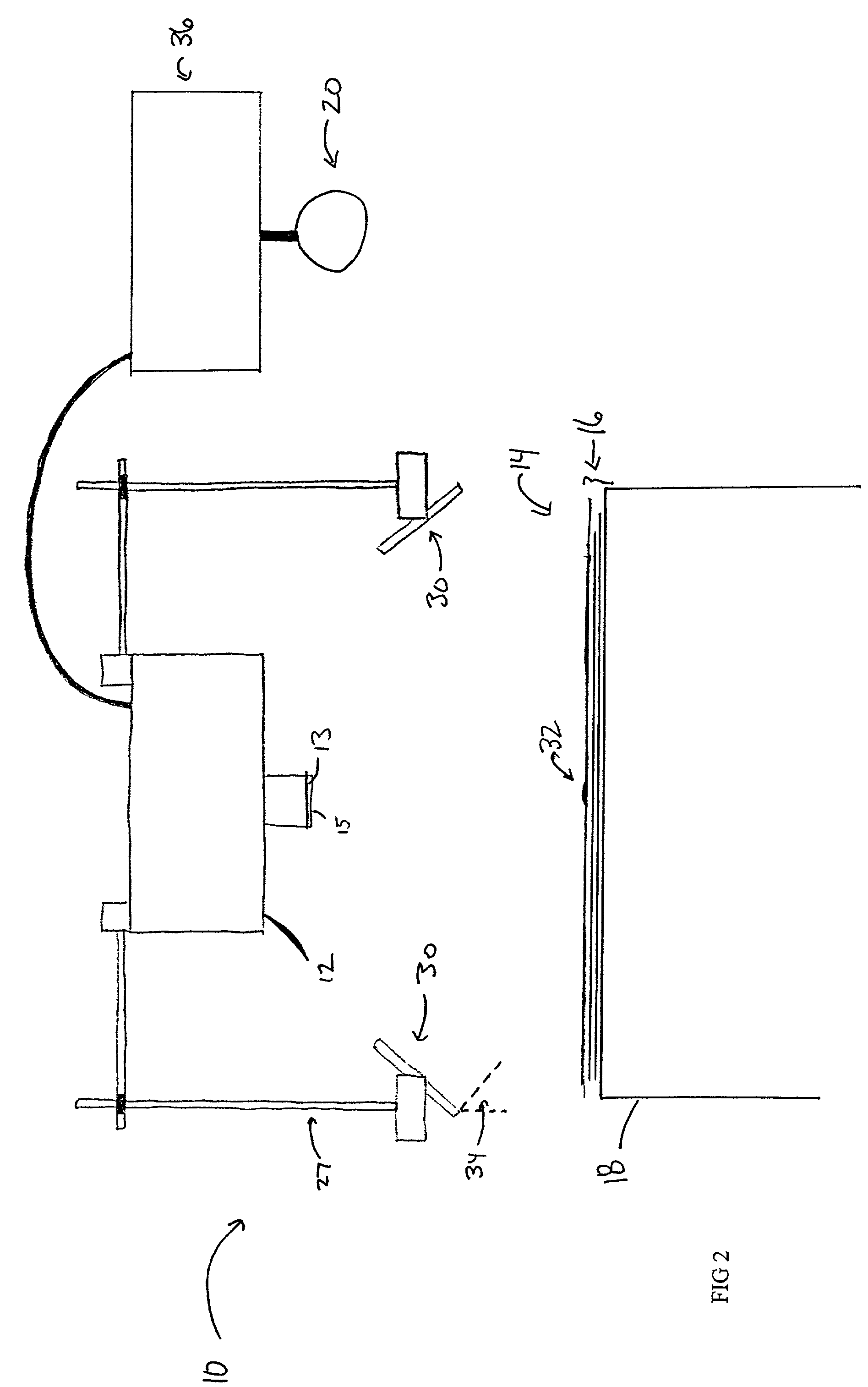
[0023]Turning first to FIGS. 1–3, a system for identifying defects in a composite structure according to the present invention is generally referred to as numeral 10. The system 10 is positioned proximate a composite structure 14, which is comprised of a plurality of adjacent tows or strips 16 of composite tape. The strips 16 typically include a plurality of fibers embedded in a resin or other material that becomes tacky or flowable upon the application of...


PUM

PropertyMeasurementUnit
Angleaaaaaaaaaa
Angleaaaaaaaaaa
Poweraaaaaaaaaa

Abstract

A system and method for identifying defects in a composite structure is provided. The system includes a camera for receiving images of the composite structure, a processor for manipulating the images and outputting a response based on the images, and a light source for illuminating the composite structure. Advantageously, the light source is positioned at an oblique angle relative to the composite structure and comprises an infrared component that is differently reflected by defects in the composite structure than from portions of the composite structure that are defect free. Based on the response provided by the processor, defects that meet predetermined criteria can be identified.

Description

GOVERNMENT RIGHTS[0001]The United States Government may have rights in this invention pursuant to Contract No. F33615-98-C5104 awarded by the Department of the Air Force.FIELD OF THE INVENTION[0002]The present invention relates generally to the fabrication of composite structures, and more particularly to systems and methods adapted for locating defects during fabrication of composite structures.BACKGROUND OF THE INVENTION[0003]Composite structures have been known in the art for many years. Although composite structures can be formed in many different manners, one advantageous technique for forming composite structures is a fiber placement or automated collation process. According to conventional automated collation techniques, one or more ribbons of composite material (also known as composite tows) are laid down on a substrate. The substrate may be a tool or mandrel, but, more conventionally, is formed of one or more underlying layers of composite material which have been previousl...

Claims


Application Information

Patent Timeline
IPC IPC(8): G06K9/00G06T5/00G06T7/00
CPCG06T7/0004G01N21/88G06T2200/24G06T2207/10048G06T2207/20148G01N2021/888G01N21/8806G01N2021/8472G06T2207/30124G06T7/136B29C70/386
Inventor ENGELBART, ROGER W.HOLMES, SCOTT T.WALTERS, CRAIG
Owner THE BOEING CO
Why Eureka
Try Eureka