Method for receiving radio frequency signal and a receiver device

a radio frequency signal and receiver technology, applied in the direction of polarisation/directional diversity, transmission monitoring, instruments, etc., can solve the problems of complex mechanical arrangement, inability of the antenna to detect electro-magnetic radiation, dynamic changes in the received radiation, etc., to improve the properties of the received signal, easy to produce, and adapt fast to the effect of receiving signal changes

Active Publication Date: 2007-01-30
NOKIA TECHNOLOGLES OY
View PDF16 Cites 33 Cited by
  • Summary
  • Abstract
  • Description
  • Claims
  • Application Information

AI Technical Summary

Benefits of technology

[0026]The interleaving signal components are sampled to produce digitized signals, which are here called sampled signal components. These sampled signal components are complex-valued, since they also have an In-phase and a Quadrature-phase component. Using the sampled signal components, whereof a first sampled signal component corresponds to the properties of the first antenna and a second sampled signal component corresponds to the properties of the second antenna, it is possible to construct a combined signal matching better the properties of the received signal. For example, by choosing a suitable linear combination of the first and second intermediate sampled signals, it is possible to produce a signal corresponding to any desired polarization properties. The combined signal can be easily produced, for example, using digital signal processing. One or both of the sampled signals are multiplied with a suitable complex factor to produce a correct phase shift and correct amplitude, and thereafter the sampled signal components are summed. The coefficients of the linear combination are typically complex valued. Of course, some values of the coefficients may be real. Term coefficient in this description refers to the coefficients of the linear combination producing the combined signal.
[0027]Because the adaptation to properties of the received signal occurs by modifying digitized signals, adaptation to changes in, for example, the polarization or angular properties is quite easily carried out: only the complex coefficients of the linear combination of the signals need to be changed. It is possible to adapt fast to changes in the received signal; this is one of the advantages of the invention. The values for the coefficients are selected so that they produce a better quality for the combined signal than is the quality of either of the received signals. Suitable values for the coefficients can be found, for example, by maximizing the signal-to-noise ratio of the combined signal. The effect of multipath propagation may alternatively be minimized, or coefficient values can be chosen so that they take into account both the signal-to-noise ratio and the multipath propagation. When the polarization changes in a received signal are related to reflections of the signal, there usually is a limited number of candidates for the coefficient values, and the selection of a proper set of values is quite easy.

Problems solved by technology

In this case the antenna cannot detect the electro-magnetic radiation.
The problem may, however, be the dynamical changes in the received radiation.
One alternative is to modify the physical properties of the antenna, but this may require quite complex mechanical arrangements and most probably the modifications cannot be made at a high rate.
Additional components increase the cost and manufacturing complexity of a device.
Furthermore, if the GPS receiver is intended to be integrated within a cellular phone, the number of components should be kept as low as possible because of power consumption and space requirements.
A further problem is that with the system presented in EP 416 264, a GPS receiver, which is designed to work indoors, should have more than two antennas: a pair of orthogonal antennas is needed for each GPS signal that is to be received at a time.

Method used


Image

  • Method for receiving radio frequency signal and a receiver device
  • Method for receiving radio frequency signal and a receiver device
  • Method for receiving radio frequency signal and a receiver device

Examples


Embodiment Construction

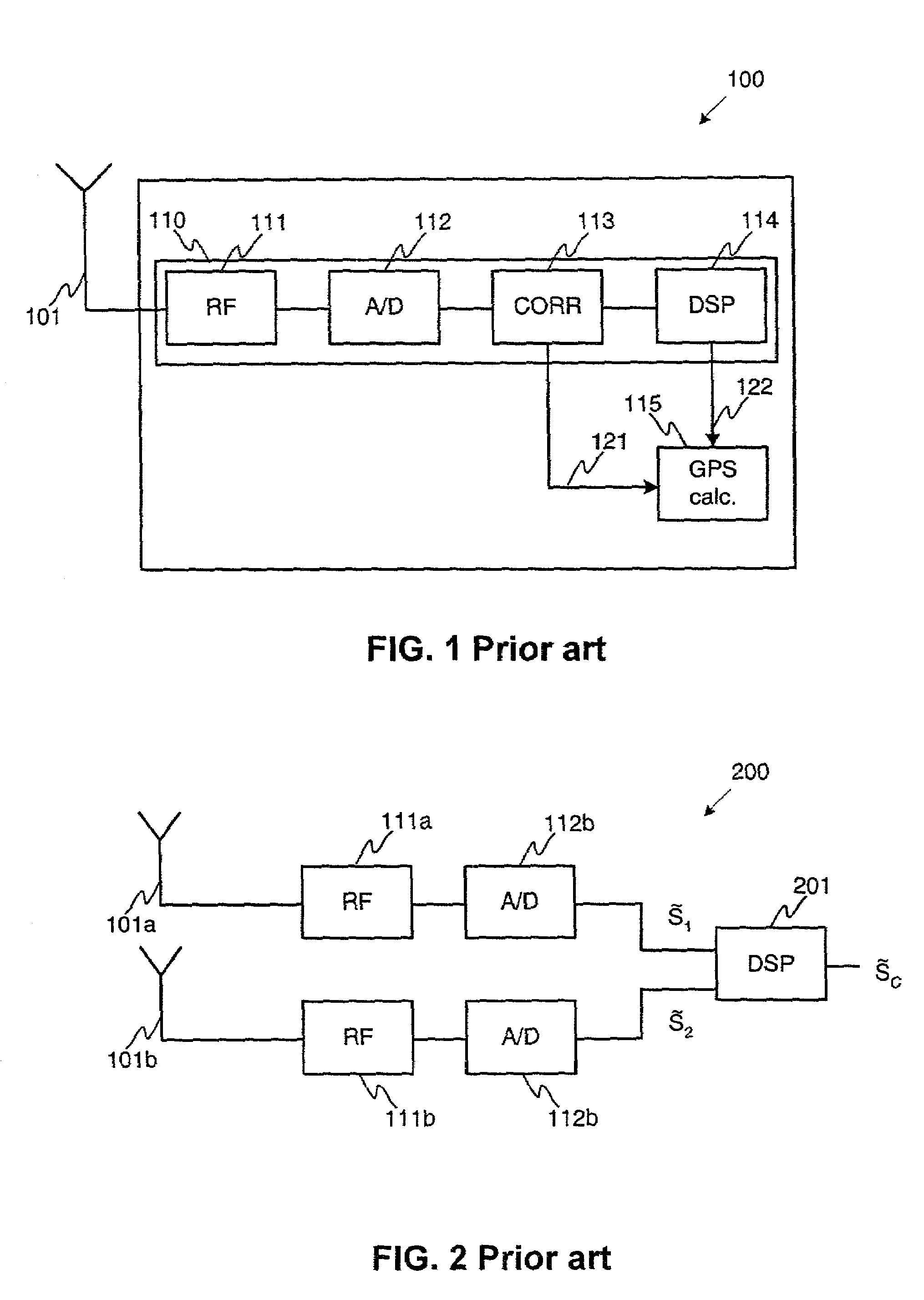
[0044]FIGS. 1–2 are discussed in detail in the description of radio receivers according to prior art.

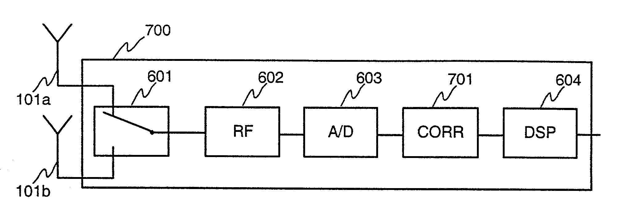
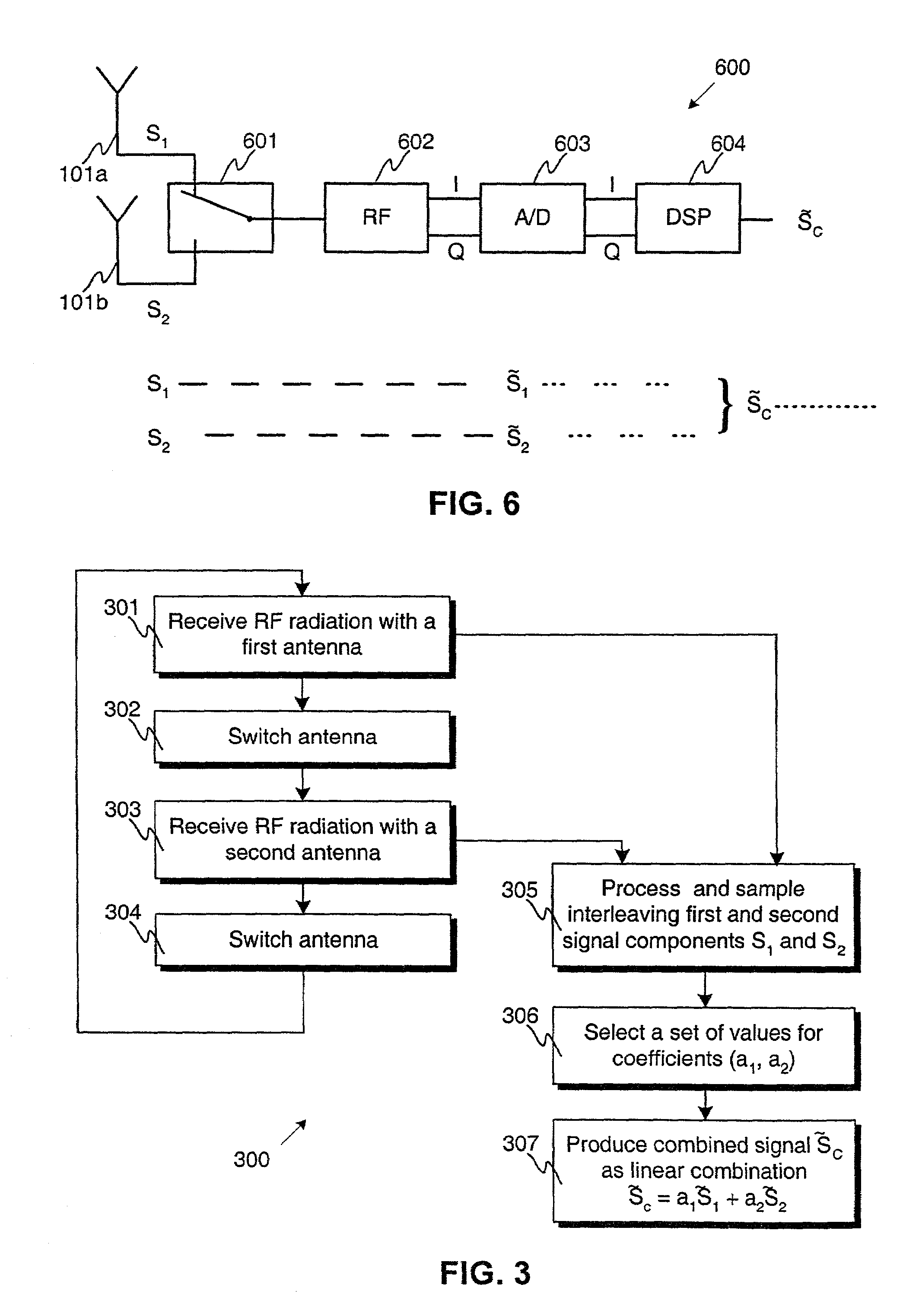
[0045]FIG. 3 illustrates a flowchart of a method 300 for receiving radio signal according to a first preferred embodiment of the invention. In step 301 radio frequency radiation is received using a first antenna. In step 302 the antenna using which radiation is received is switched to a second antenna, which has different properties than the first antenna. The polarization properties of the antennas or the location of the antennas, for example, may be different. In step 303 radio frequency radiation is received using the second antenna, and in step 304 the antennas are again switched. In a method according to the first preferred embodiment of the invention, the steps 301–304 can be carried out all the time. A first received signal component S1, which corresponds to the first antenna, and a second received signal component S2, which corresponds to the second antenna, are interleaved i...


PUM


Abstract

In a method (300) for receiving a radio signal, there are steps of: receiving (301, 303) first and second received signal components by use of first and second antennas having different properties; processing (305) a received signal component to produce a sampled signal component; producing (307) at least one combined signal, which is a linear combination of at least two sampled signal components; and selecting (306) at least one set of complex values for coefficients of the linear combination so that a quality of a combined signal is at least equal to the quality of that sampled signal component having the best quality. Furthermore, the antennas are alternately connected (302, 304) via a switching element to radio frequency means so that received signal components are interleaving and so that first and second parts of a certain piece of transmitted information are received with the first and second antennas, respectively. A corresponding receiver device is also presented.

Description

BACKGROUND OF THE INVENTION[0001]The invention relates in general to polarization properties of antennas. In particular the invention relates to adjusting the polarization properties of an antenna based on the polarization properties of a received signal.[0002]Electro-magnetic radiation has certain polarization properties. When receiving signals carried by radio frequency (RF) electro-magnetic radiation, generally the polarization properties of the antenna are matched to those of the incoming signal. If electro-magnetic radiation experiences a reflection, its polarization properties typically change. Therefore there may be need to adjust dynamically the polarization properties of an antenna depending on the path of the radiation from the transmitting antenna to the receiving antenna. Otherwise it is, in the worst case, possible that the polarization properties of an antenna are orthogonal to those of the electro-magnetic radiation that is received using the antenna. In this case the...

Claims


Application Information

Patent Timeline
Patent Type & Authority Patents(United States)
IPC IPC(8): H04B7/08
CPCH04B7/0822H04B7/0857H04B7/0848H04B7/10G01S19/22G01S19/36
Inventor LAHTI, SAKUKONTOLA, ILKKA
Owner NOKIA TECHNOLOGLES OY
Why Eureka
Try Eureka