Wind and solar power plant with variable high speed rotor trains

a rotor train and variable technology, applied in the direction of fluid couplings, renewable energy generation, greenhouse gas reduction, etc., can solve the problems of high cost of produced energy, need constant maintenance, and known wind power plants cannot win the competition, so as to increase suction, produce a large amount of inexpensive electrical energy, and exceed the effect of energy

Inactive Publication Date: 2007-02-06
TRUONG MINH HOANG DINH +1
View PDF18 Cites 68 Cited by
  • Summary
  • Abstract
  • Description
  • Claims
  • Application Information

AI Technical Summary

Benefits of technology

[0028]A plurality of powerful, quiet rotors is collected in one building. These rotors will not harm the environment even in the surroundings of a large city, will protect the bird population and provide a pleasant aesthetic view. The building is having a base, a roof and a plurality of horizontal stability belts, spaced apart and distributed along an imaginary vertical axis of symmetry. Each of the stability belts is formed by an upper horizontal deck, a larger in horizontal dimensions lower deck and vertical walls, connecting the upper and the lower decks and providing an inner space for electrical and mechanical equipment, for storage and for maintenance and an outer space for balconies running around a perimeter of the lower deck. Both horizontal decks are having shape of a polygon with the same number of equal angles between vertical sides, and providing a floor for the space, located above and a ceiling for the space, located below of the decks.
[0073]Another object of this invention is to place the rotors behind the walls of the shroud, the wind tunnel, the decks of the building, the protective steel nets with the purpose to minimize the impact of the power plant on the surrounding environment, to reduce the noise, the electromagnetic impulses, the wind and the sun reflections and other factors, which can be attributed to the wind power plants, working in the open places under the impact of the ambient wind.

Problems solved by technology

The currently known wind power plants can not win the competition because they do not provide reliable devices, utilizing the advantages and availability of the wind and sun as a source of energy.
Most of the known power systems, utilizing the wind and solar energy, depending on availability of a strong wind, are too small to produce electrical energy on a large scale, use only one generator for transforming the energy of the wind into electrical current, need constant maintenance, and making the cost of the produced energy too high.
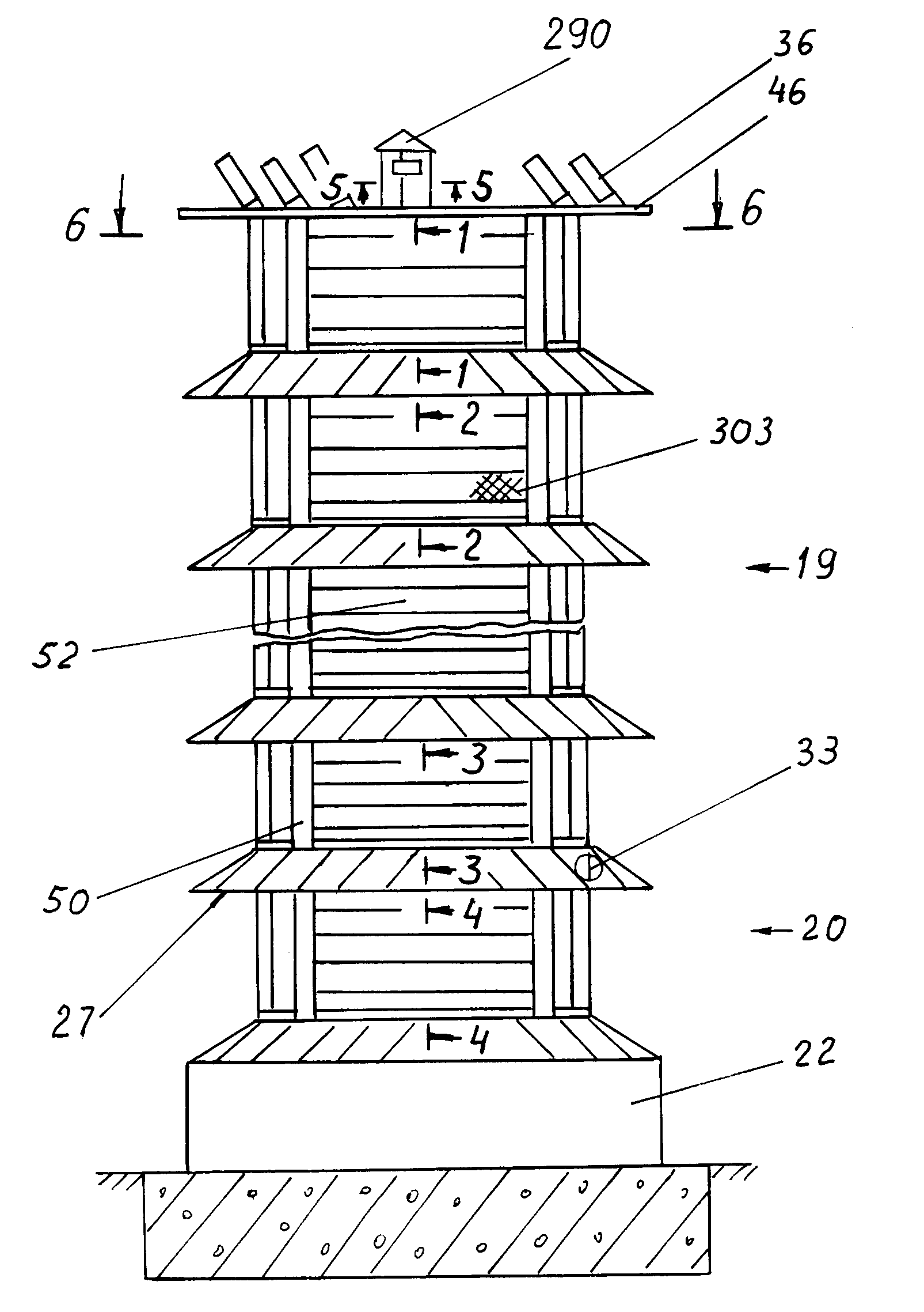
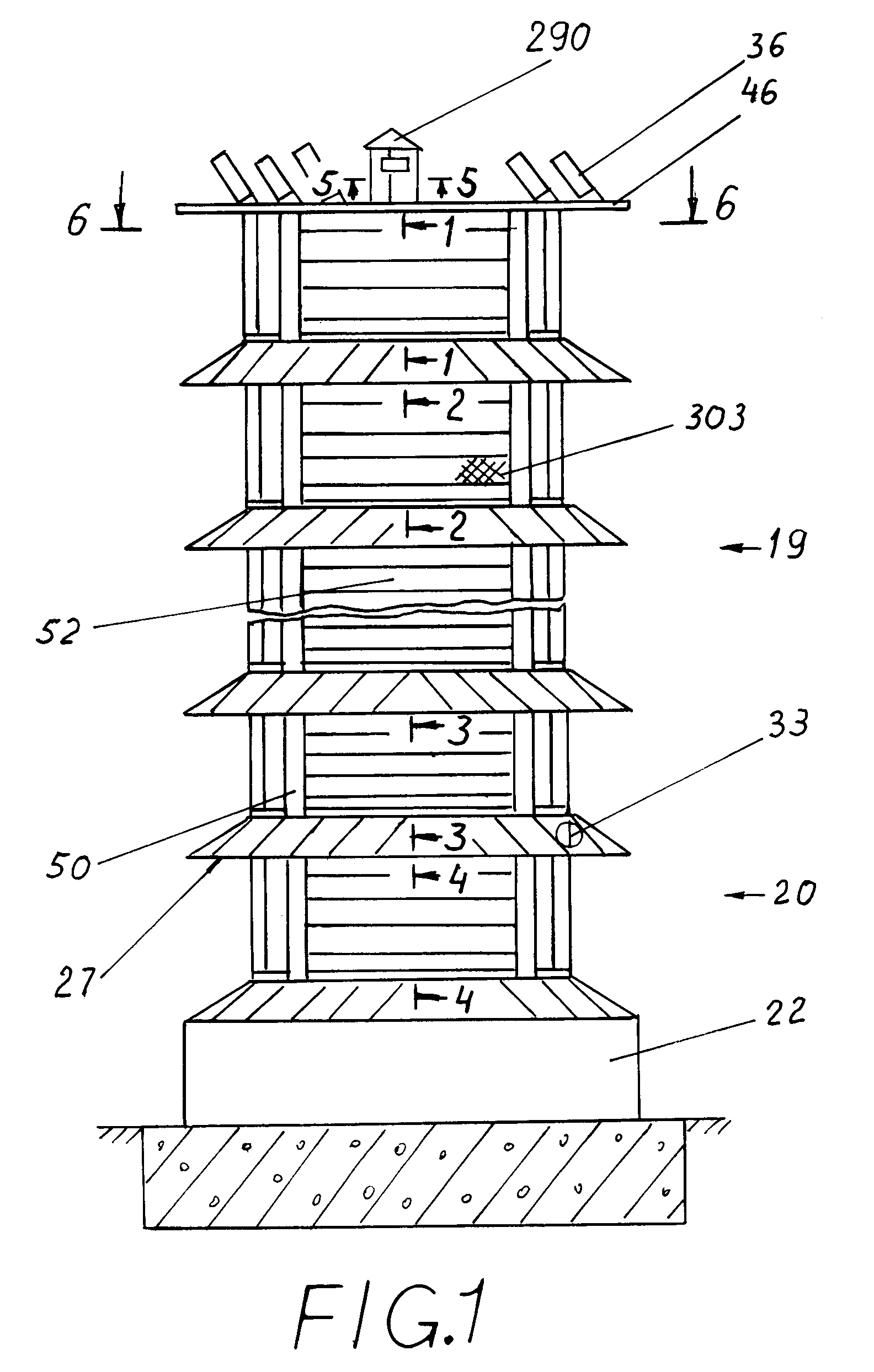
The design of the vertical shaft and the shields is too complicated and not reliable; the wind wheels are equipped with cups, instead of flat blades and thus can not provide adequate torque because the cups will be constantly filled with the air.
This large power plant can produce only a small amount of energy and definitely at a very high cost.
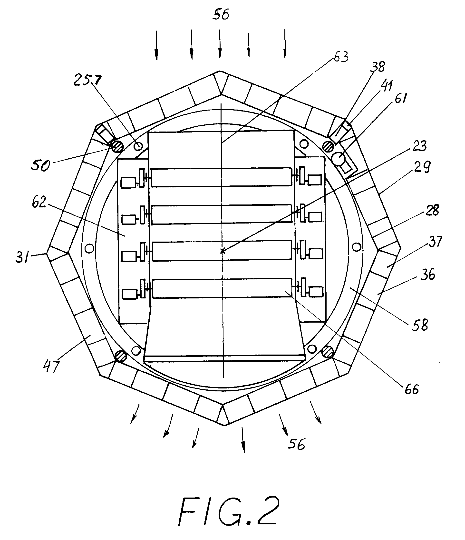
The rotors stacked one above another and connected with one vertical shaft, transferring all the collected energy to only one generator; so, the output of energy can not be cost efficient.
The weight and related stress do not allow making this shaft too high.
The rotors initially imply synchronous rotational speed (see FIG. 4), which can cause increasing vibration and can cause breakage of the system.
The space between the blades is too big, especially for a rotor with two blades, and it takes time for the wind to fill up the space with air, so the impact on one blade will be extended in time, and cause a slow rotation of the rotor.
The sharp, curved and helically pitched blades are too difficult to make and they are not be durable.
The trailing edges of the blades are difficult to make, they are thin and can be easily broken.
And any change of speed of the wind can cause slumming of the side doors, creating constant noise and turbulence of the wind flow.
The wind will lose its speed after the first pair of rotors, and will not have enough power to rotate the second and the third pair of rotors.
So, the frame for six propellers should be really big, high, and costly.
And in general, the productivity of known propeller type rotors can not be compared with other engines, using other sources of energy.
A long, twisted way for the wind flow will create large frictional forces between the wind guide and the narrowing surfaces of the twisted member and limit the power of the wind.
Sudden exhaust of the out-going air from the back side of the device will create turbulence, blocking the exit.
At the same time, too small angles of inclination of the guiding plates create bigger size of the shroud, causing increase in all of the dimensions of the plant and an increase in the cost of the plant.
On page 3 (65), O'Shanahan writes that a conduit 22 with an intake mouth (23) of 8 meters diameter and a rotor with a sweeping area of 6 meter diameter will have 350 kW of power, but the actual ratio 8 to 6, equal to 4:3, which is shown in FIG. 4 does not give such increase in the speed of the wind and not adequate to receive such power.
The system looks very big and bulky, and it will become much bigger if we will include all the structures needed to hold the tubes one inside another and to turn the structure towards the wind.
But, despite the fact that the system is relatively big, the output of the energy will be limited.
The relatively long blades as well as supportive structures, not shown in the drawing, but needed to support the rotors and generators, will cause a turbulent wind flow and an additional loss in efficiency.
Despite that the system is relatively big, the output of the energy still will be limited.
These new means do not produce additional eddies because the restricting surfaces of our invention positioned in flat planes unlike the cited patent, having curved surfaces around the slots which will create additional turbulences.
This patent is similar to the already discussed U.S. Pat. No. 6,249,059, and has similar disadvantages common to patents having propellers mounted in venturi type tube.
The resulting torque will be equal to the difference between the two mentioned, and it can be too small to produce adequate energy.
The blades, comprising a single, separately standing long plate can not transfer a large rotating torque at a high rotational speed, causing vibration and loss of stability of the rotor.
We don't think that people living in this building will approve this idea.
The blades of the rotor are mostly not covered and will produce noise, blasts of wind and vibration.
Also possible are electro magnetic and radio impulses and interferences which residents of the building will not approve.

Method used


Image

  • Wind and solar power plant with variable high speed rotor trains
  • Wind and solar power plant with variable high speed rotor trains
  • Wind and solar power plant with variable high speed rotor trains

Examples


Embodiment Construction

[0163]Basically, the operation of all of the embodiments of the invention is the same. Each of the rotor trains shown, for example, in FIGS. 3 and 18, is having the high rectangular entrance 118 for the wind 56. The steams of the wind are gradually contracted by the converging nozzle panels 141 and 142 to a low rectangular wind way 140, where the wind, pressed in the vertical direction, flow much faster compared with the speed of the ambient wind. At the exit of the diffuser 120 the gradually diverging plates 153 and the diverging parts of the vertical walls 121 allow the air, flowing out of the wind way 140, to gradually expand in the vertical and the horizontal dimensions to the volume, bigger than it had at the entrance 118, creating a zone of low static air pressure in the diffuser 120 and a tunnel suction in the wind way 140, causing increase in the speed of the wind inside the wind way. An additional, enlarged zone of low static air pressure is provided by the super-diffuser 1...


PUM


Abstract

A wind and solar power plant, producing electrical energy at any scale, site, and level above the ground, and with almost no wind, comprises rotor trains, mounted on decks of a garage-like building, each rotor train having a plurality of rotors positioned between a shroud and a wind tunnel. The wind is accelerated in a low middle part of the wind tunnel while flows from a high entrance towards a higher and wider exit. The blades of the rotors protrude into the middle part of the wind tunnel causing fast rotation of the rotors around horizontal axes. A super-diffuser, a booster and a wind tunnel are increasing the power of the wind and rotors in hundreds of times. Each rotor train comprises up to six rotors connected with twelve electrical generators. Electrical energy can be also produced by solar panels, mounted on the balconies and on the roof of the building.

Description

CROSS-REFERENCE TO RELATED APPLICATIONS[0001]Related and not relied upon U.S. Pat. No. 6,749,393, Jun. 15, 2004 awarded to Y. Sosonkina.STATEMENT REGARDING FEDERALLY SPONSORED RESEARCH OR DEVELOPMENT[0002]Not Applicable.REFERENCE TO SEQUENCE LISTING, A TABLE, OR A COMPUTER PROGRAM LISTING COMPACT DISK APPENDIX[0003]Not Applicable.BACKGROUND OF THE INVENTION[0004]The invention relates to the wind and solar power plants, specifically to such plants which utilize a plurality of rotors, having horizontal axes of rotation, disposed in one building, having means for positioning these rotors towards the direction of the wind and having means for accelerating and guiding the wind towards these rotors. The invention also relates to the power plants utilizing the energy of the sun by converting this energy collected by solar panels into electrical current.[0005]The invented power plant can produce electrical energy at any scale and at a lower cost compared to power plants, that utilize other ...

Claims


Application Information

Patent Timeline
Patent Type & Authority Patents(United States)
IPC IPC(8): F03D3/02
CPCF03D3/0454F03D9/007F03G6/001Y02E10/74Y02B10/30Y02B10/70Y02E10/465F05B2220/708Y02E10/46Y02E10/728F03D9/25F03D9/45F03D9/35F03D80/70F03D3/0463F03D3/02
Inventor TRUONG, MINH-HOANG DINHSOSONKINA, YEVGENIYA
Owner TRUONG MINH HOANG DINH
Why Eureka
Try Eureka