Pyrolysis heater

a heater and pyrolysis technology, applied in water-tube boilers, rotary drum furnaces, burners, etc., can solve the problems of difficult heat transfer into the reaction tube, higher flux, and higher temperature of the reaction tube, so as to prevent the rollover effect of flam

Active Publication Date: 2007-02-06
ABB LUMMUS GLOBAL INC
View PDF18 Cites 18 Cited by
  • Summary
  • Abstract
  • Description
  • Claims
  • Application Information

AI Technical Summary

Benefits of technology

[0010]The present invention relates to pyrolysis heaters, particularly for the cracking of hydrocarbons for the production of olefins, with a burner arrangement in the firebox including fuel injection ports to straighten the vertical flame and prevent flame rollover. In particular, the invention involves the introduction of a portion of the fuel supply along the walls of the heater at locations above the main burners and between the walls and the main burner flame.

Problems solved by technology

Given the limitation of small tube volume to achieve short residence times and the high temperatures of the process, heat transfer into the reaction tube is difficult.
In most cases, the allowable maximum tube metal temperatures limit the extent to which residence time can be reduced as a result of a combination of higher process temperatures required at the coil outlet and the reduced tube length (hence tube surface area) which results in higher flux and thus higher tube metal temperatures.
This in turn will lead to higher rates of coking (over-reaction) inside the tube at that point and limit the run-length or it will lead to carburization of the coil and mechanical failure at that point.
Either way, it is not a desirable result.
However, that was not always true and is not generally true for the new lower NOx combustion type burners.
This staged or delayed combustion results in lower maximum flame temperatures and reduced NOx production.
Thus the combination of slower combustion and lower recirculation zone height lead to flame rollover and the severe negative consequences on the process coil.

Method used


Image

  • Pyrolysis heater
  • Pyrolysis heater
  • Pyrolysis heater

Examples


Embodiment Construction

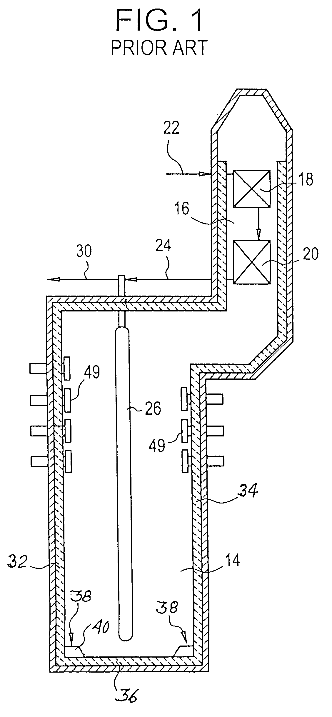
[0020]Before describing the details of the preferred embodiments of the present invention, a typical prior art pyrolysis heater will be described. FIG. 1 shows a cross section of such a prior art heater. This heater has a radiant heating zone 14 and a convection heating zone 16. Located in the convection heating zone 16 are the heat exchange surfaces 18 and 20 which in this case are illustrated for preheating the hydrocarbon feed 22. This zone may also contain heat exchange surface for producing steam. The preheated feed from the convection zone is fed at 24 to the heating coil generally designated 26 located in the radiant heating zone 14. The cracked product from the heating coil 26 exits at 30.

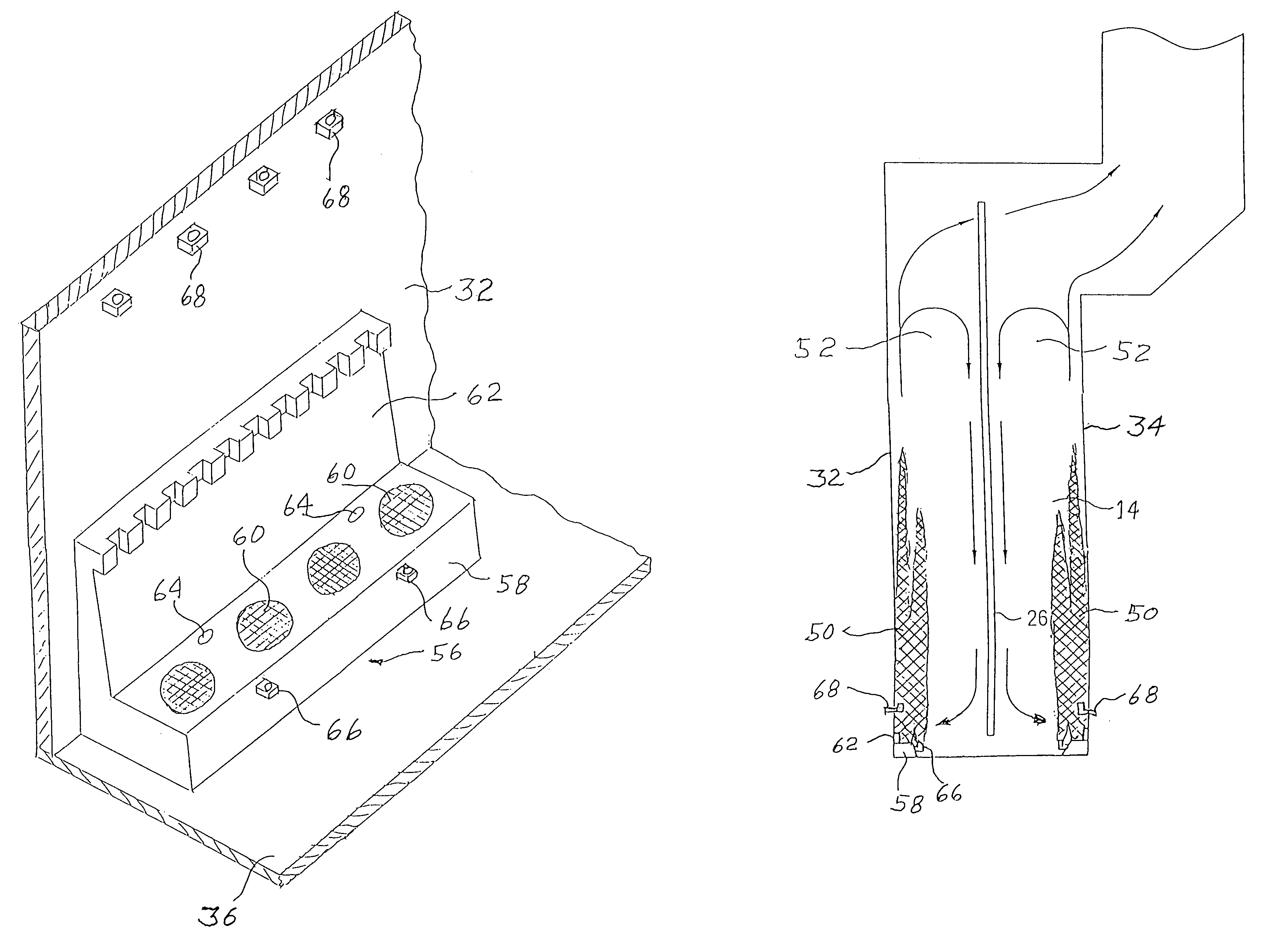
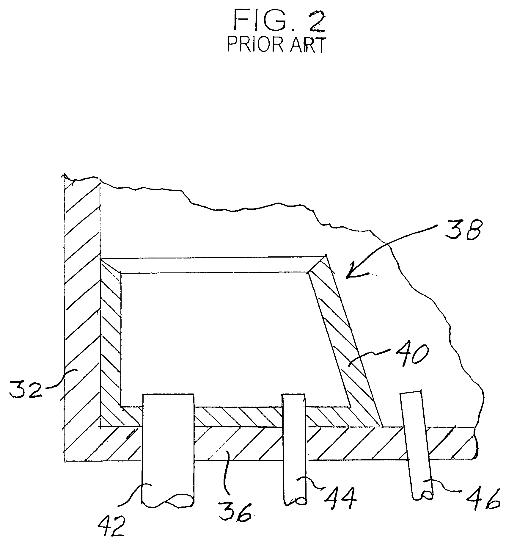
[0021]The radiant heating zone 14 comprises walls designated 32 and 34 and the floor or hearth 36. Mounted on the floor against the walls are the vertically firing main or hearth burners generally designated 38. These burners 38 are spaced along the wall. The size of a burner is determined ...


PUM

PropertyMeasurementUnit
temperatureaaaaaaaaaa
outlet temperaturesaaaaaaaaaa
temperaturesaaaaaaaaaa

Abstract

A pyrolysis heater particularly for the cracking of hydrocarbons in the production of olefins has a burner arrangement in the firebox which includes staged combustion low NOx hearth burners firing upwardly in the firebox adjacent to the walls. Wall stabilizing gas fuel injection tips, located at an elevation above the hearth burners, inject fuel upwardly between the walls and the flame from the hearth burners. This prevents rollover of the flame onto the process heater coil and overheating of the coil.

Description

BACKGROUND OF THE INVENTION[0001]The present invention relates to a heater for the pyrolysis of hydrocarbons and particularly to a heater for the steam cracking of paraffins to produce olefins. In particular, the invention relates to a firing arrangement to prevent flame rollover and impingement on the process coils most particularly for staged combustion for low NOx production.[0002]The steam cracking or pyrolysis of hydrocarbons for the production of olefins is almost exclusively carried out in tubular coils located in fired heaters. The pyrolysis process is considered to be the heart of an olefin plant and has a significant influence on the economics of the overall plant.[0003]The hydrocarbon feedstock may be any one of the wide variety of typical cracking feedstocks such as methane, ethane, propane, butane, mixtures of these gases, naphthas, gas oils, etc. The product stream contains a variety of components the concentration of which are dependent in part upon the feed selected....

Claims


Application Information

Patent Timeline
Patent Type & Authority Patents(United States)
IPC IPC(8): B01J8/04C10G9/14C10G9/36F27B7/00B01J19/00C10G9/20F23D14/02
CPCC10G9/20C10G2400/20B01J19/00F23D14/02C10G9/00
Inventor PLATVOET, ERWIN M. J.GARTSIDE, ROBERT JOHNPONZI, PETER ROBERTCHAPMAN, PAULMCCARTHY, FRANK D.
Owner ABB LUMMUS GLOBAL INC
Why Eureka
Try Eureka