Bandpass filter with tunable resonator

a bandpass filter and resonator technology, applied in the field of radio frequency (rf) electronics, can solve the problems of longer talk time and battery life, and achieve the effects of reducing the size, weight or cost of the handset, and less insertion loss

Inactive Publication Date: 2007-02-06
KYOCERA CORP
View PDF185 Cites 36 Cited by
  • Summary
  • Abstract
  • Description
  • Claims
  • Application Information

AI Technical Summary

Benefits of technology

[0021]Thus, a low insertion loss tunable bandpass and duplexer are provided, which are smaller and have less insertion loss than a fixed tuned bandpass filter covering the same passband. The space savings in a wireless handset can be used to provide other desired functions and properties, or their use can simply reduce the size, weight, or cost of the handset. Additionally, the savings in insertion loss result in a longer talk time and battery life.

Problems solved by technology

Additionally, the savings in insertion loss result in a longer talk time and battery life.

Method used


Image

  • Bandpass filter with tunable resonator
  • Bandpass filter with tunable resonator
  • Bandpass filter with tunable resonator

Examples


Embodiment Construction

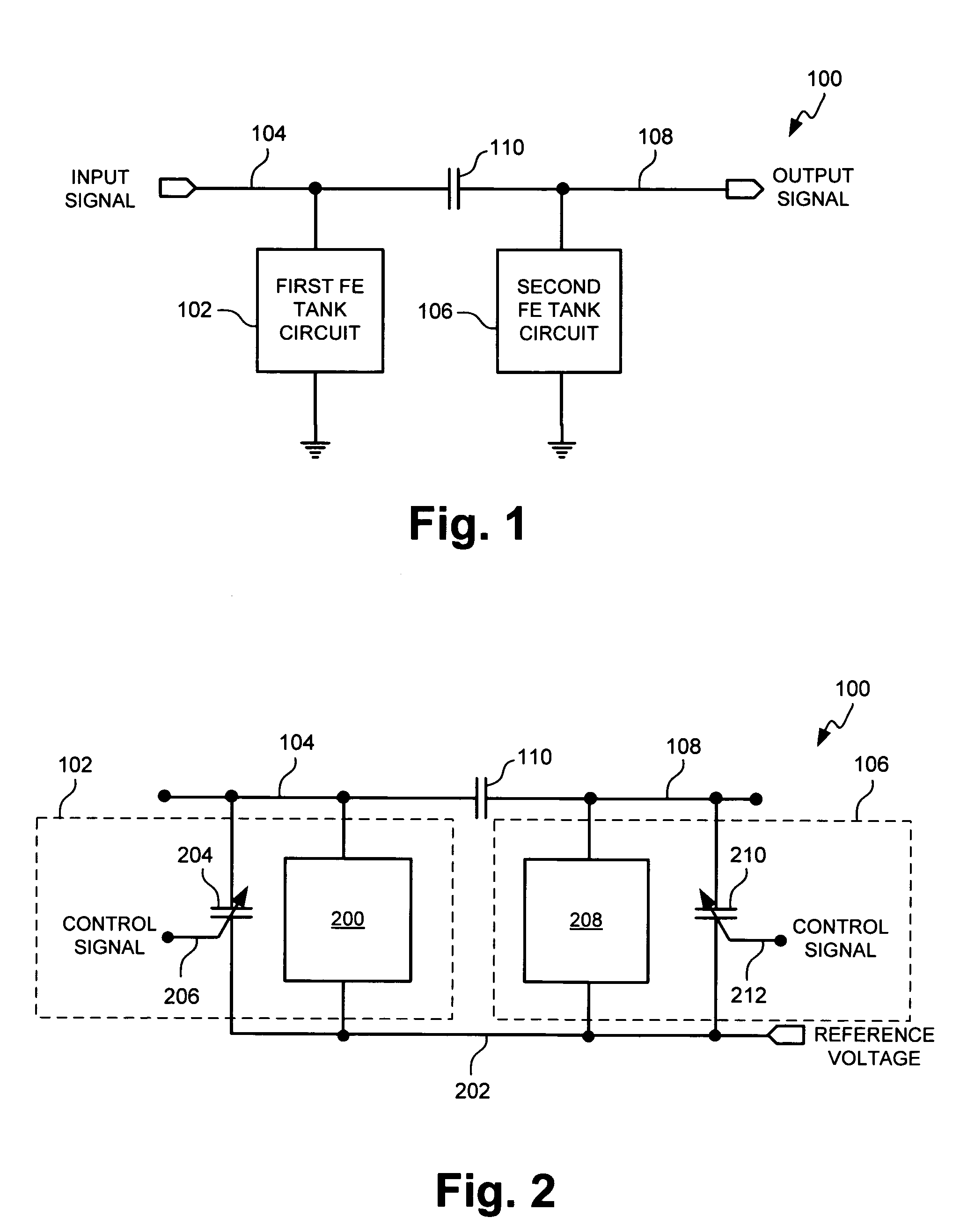
[0037]FIG. 1 is a schematic diagram of a tunable bandpass filter. The filter 100 comprises a first shunt-connected ferroelectric (FE) tunable tank circuit 102 having a first node 104 to accept an input signal. A second shunt-connected FE tunable tank circuit 106 has a second node 108 to supply a bandpass filtered signal. A first capacitor 110 is connected in series between the first node 104 and the second node 108.

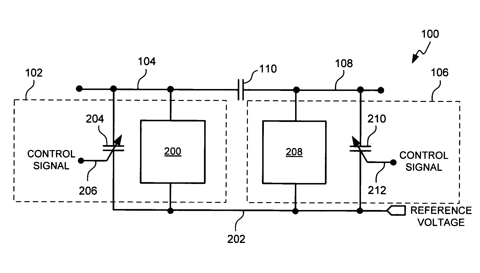
[0038]FIG. 2 is a schematic diagram illustrating a first variation of the bandpass filter of FIG. 1. In this variation the first tank circuit 102 comprises a first resonator 200 having an input connected to the first node 104 and an output connected to a reference voltage 202. For example, the reference voltage can be an AC or DC ground. A second capacitor 204 has an input connected to the first node 104, an output connected to the reference voltage 202, and an input to accept a control signal on line 206. The second capacitor 206 includes an FE material with a dielectric...


PUM


Abstract

A tunable bandpass filter is provided that comprises a first shunt-connected ferroelectric (FE) tunable tank circuit having a first node to accept an input signal. A second shunt-connected FE tunable tank circuit has a second node to supply a bandpass filtered signal. A first capacitor is connected in series between the first and second nodes. In one aspect, the first tank circuit comprises a first resonator connected to the first node, and a fourth capacitor connected between the first resonator and a reference voltage. The fourth capacitor is a tunable FE capacitor. Typically, a fifth capacitor is connected between the first node and the reference voltage. Likewise, the second tank circuit comprises a second resonator connected to the second node, and a sixth (FE) capacitor connected between the second resonator and the reference voltage. A seventh capacitor is connected between the second node and the reference voltage.

Description

RELATED APPLICATIONS[0001]This application is a continuation-in-part of U.S. application Ser. No. 10 / 981,814, filed Nov. 5, 2004, which is a continuation of U.S. application Ser. No. 10 / 076,171, filed Feb. 12, 2002, now U.S. Pat. No. 6,816,714, which claims the benefit of U.S. Provisional Application Ser. No. 60 / 283,093, filed Apr. 11, 2001, the disclosures of which are hereby incorporated by reference. In addition, this application relates to U.S. application Ser. No. 09 / 904,631 filed on Jul. 13, 2001, now U.S. Pat. No. 6,690,176, U.S. application Ser. No. 09 / 912,753 filed on Jul. 24, 2001, now U.S. Pat. No. 6,639,491, U.S. application Ser. No. 09 / 927,732 filed on Aug. 8, 2001, U.S. application Ser. No. 09 / 927,136, filed on Aug. 10, 2001, now U.S. Pat. No. 6,825,818, U.S. application Ser. No. 10 / 044,522, filed on Jan. 11, 2002, now U.S. Pat. No. 6,737,930, and U.S. application Ser. No. 10 / 077,654, filed on Feb. 14, 2002, the disclosures of which are hereby incorporated by reference...

Claims


Application Information

Patent Timeline
Patent Type & Authority Patents(United States)
IPC IPC(8): H04B1/16H03H7/00H03H7/01H03J3/08
CPCH03H7/0161H03H7/1791H03J3/08
Inventor TONCICH, STANLEY S.FABREGA-SANCHEZ, JORGE
Owner KYOCERA CORP
Why Eureka
Try Eureka