Transmitting electric power control method in the CDMA system

a technology of cdma system and transmission method, applied in the direction of transmission monitoring, power management, multiplex communication, etc., can solve the problems of inability to perform output adjustment using an outer loop, the accuracy of electric power control itself is also affected, and the transmission of electric power cannot be guaranteed. , to achieve the effect of reducing the durability of surrounding electric waves, reducing the number of transmission lines, and ensuring data communication quality

Inactive Publication Date: 2007-02-06
LENOVO INNOVATIONS LTD HONG KONG
View PDF16 Cites 4 Cited by
  • Summary
  • Abstract
  • Description
  • Claims
  • Application Information

AI Technical Summary

Benefits of technology

[0013]To solve the above-described problems, in this invention, transmitting electric power is compulsorily lowered to prevent the occurrence of a near/far problem if the time when packet data does not exist passes more than a fixed time and transmitting electric power from a terminal device to a base station exceeds a fixed range. On the other hand, if transmitting electric power from a term

Problems solved by technology

Therefore, a near/far problem, in which transmission signals from the long-distance mobile station are buried in ones from the nearby mobile station.
This problem may occur at not only base stations but also mobile stations.
The above-described re-released patent remains problems that interference electric power accuracy falls if the output ratio of receiving signal to disturbance wave for a desired wave is small, resulting that the accuracy of electric power control itself also falls.
In addition, there are the following problems resulted from that the time when downlink packet data does not exist continues in packet communications on a dedicated channel in transmitting electric power control at a base station in the CDMA system.
Therefore, it is the first problem that output adjustment using an outer loop cannot be performed.
As a result, the measurement of a block error rate and receivi

Method used


Image

  • Transmitting electric power control method in the CDMA system
  • Transmitting electric power control method in the CDMA system
  • Transmitting electric power control method in the CDMA system

Examples


first embodiment

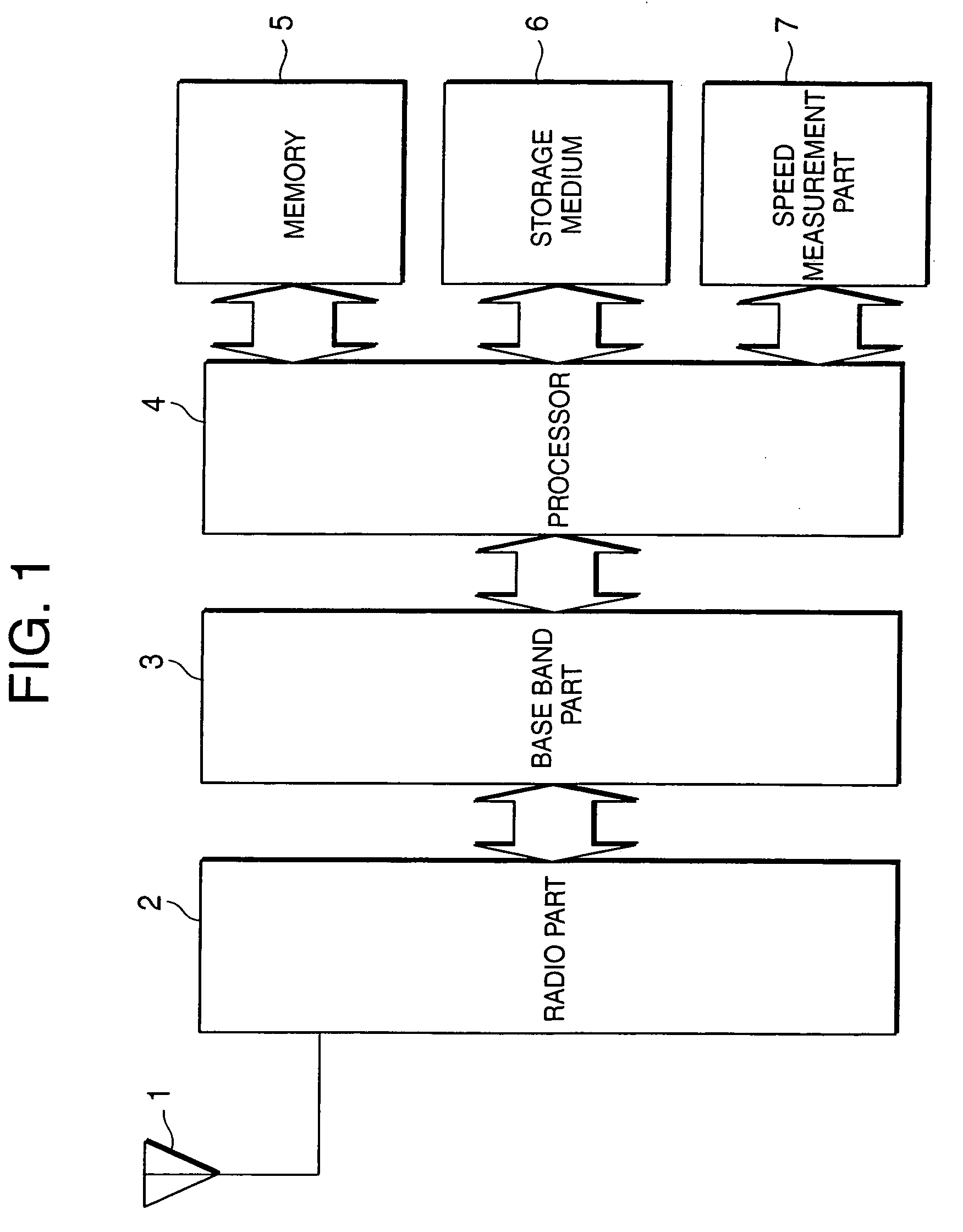
[0030]FIG. 1 is a block diagram to show a mobile radio device according to this invention. Hereinafter, a CDMA cellular phone device, with which a CDMA system is employed, will be used as a mobile radio device.

[0031]A CDMA cellular phone device shown in FIG. 1 is composed of an antenna 1, a radio part 2, a base band part 3, a processor 4, memory 5, a storage device 6 and a speed measurement part 7.

[0032]The radio part 2 has a modulation / demodulation circuit, which modulates and demodulates radio signals transmitted and received through the antenna 1.

[0033]The base band part 3 includes an encoder, which performs error correction encoding for data transmitted from the processor 4, a circuit, which divides into radio frames, and a circuit, which performs orthogonal code diffusion. In addition, the base band part 3 also includes a circuit, which performs orthogonal code reverse diffusion for received data demodulated at the radio part 2, a circuit, which measures power, a circuit, which...

second embodiment

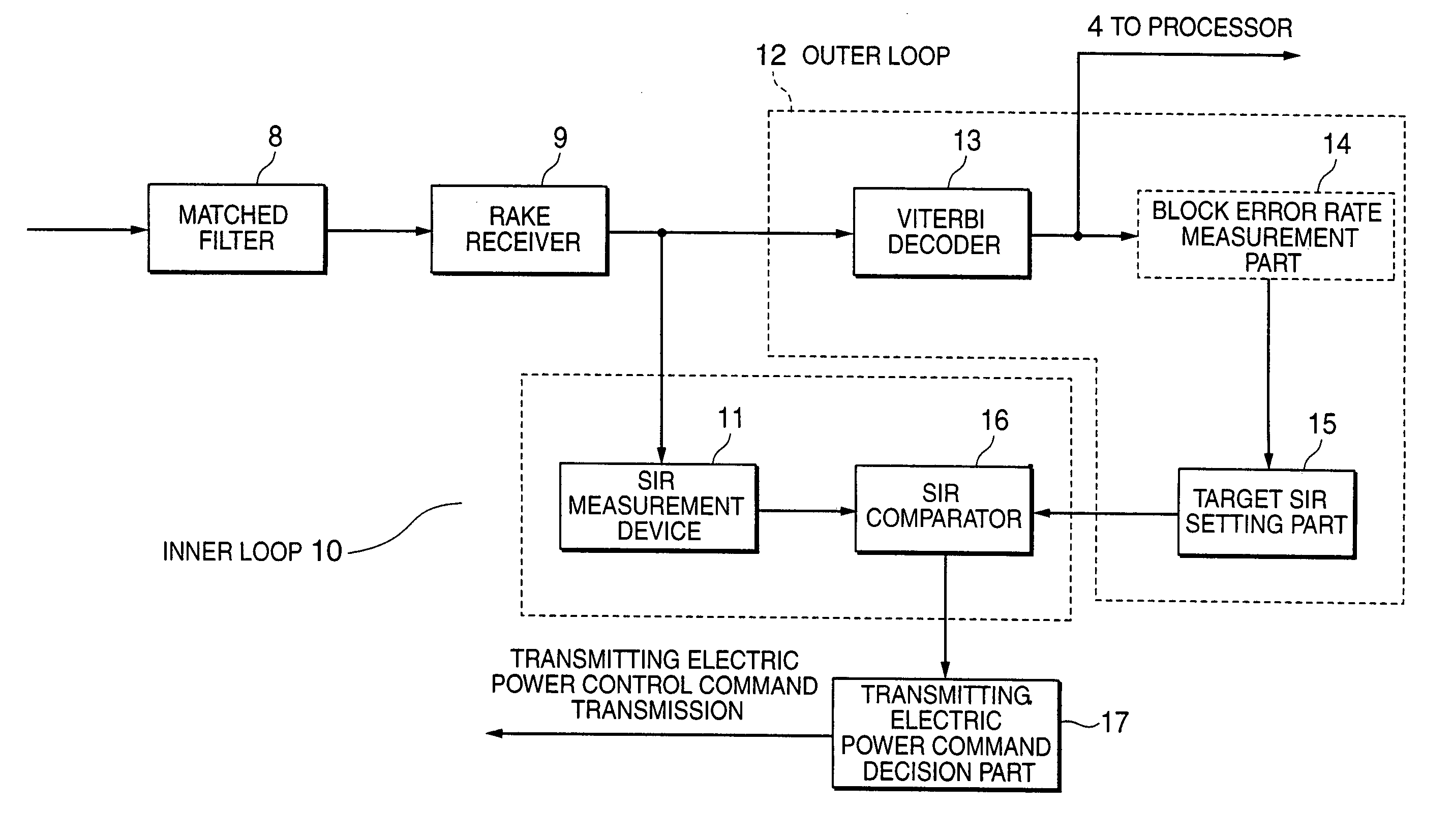
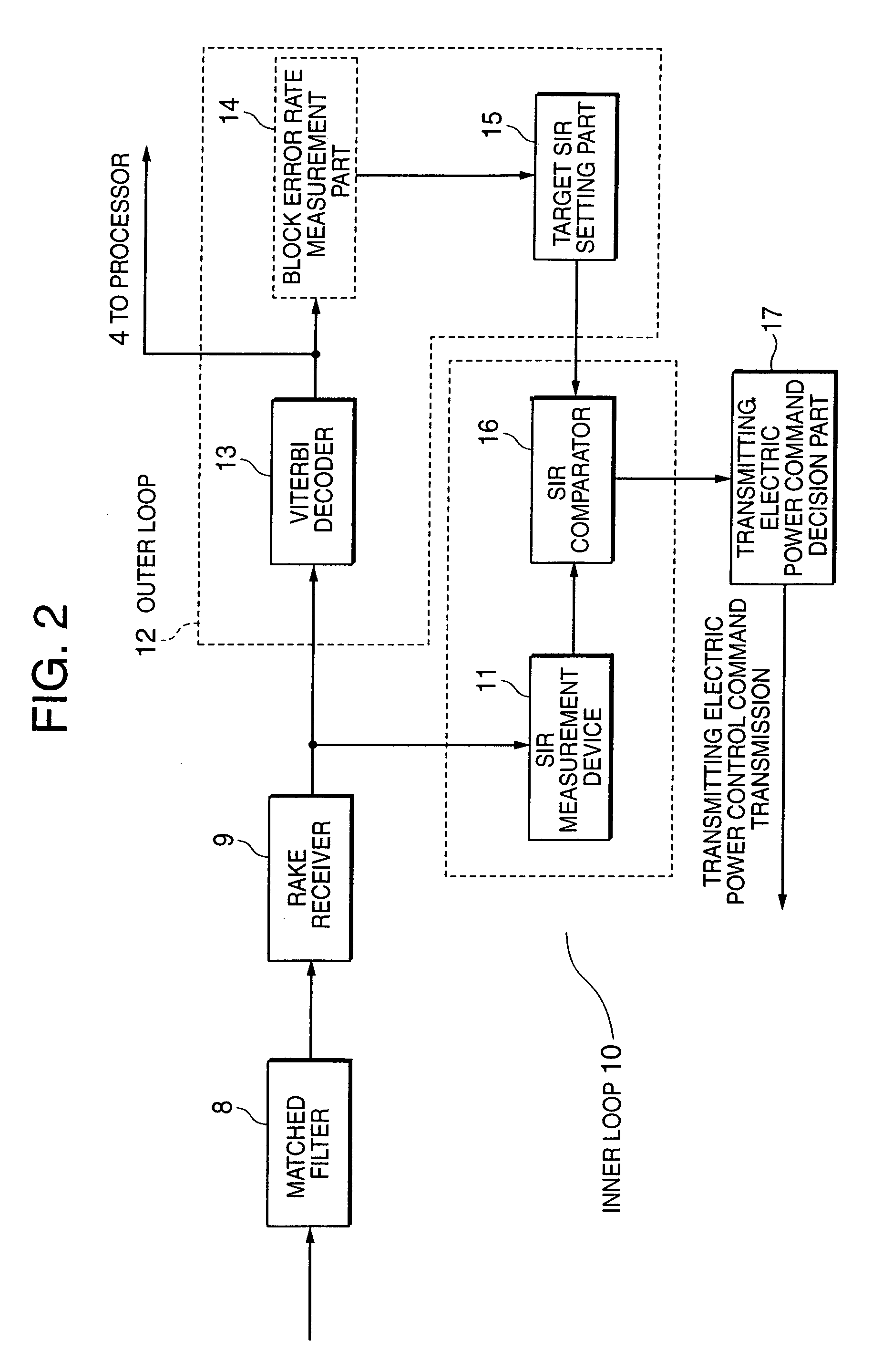
[0067]The CDMA cellular phone device under packet communications on a dedicated channel in the second embodiment processes receiving data from the radio part 2 with orthogonal code reverse diffusion, radio frame combination, and error correction decoding at the base band part 3. Subsequently, the Viterbi decoder 13 notifies the processor 4 of “downlink receiving data exists” and the receiving data (S801). For base station transmitting electric power control (hereafter, called as outer loop control), the block error rate measurement part 14 in the processor 4 measures a receiving block error rate, and compares with downlink receiving quality to determine target SIR (S802).

[0068]Then, the processor 4 sets the target SIR into the target SIR measurement part 15 in the base band part 3 (S803).

[0069]The SIR measurement device 11 in the base band part 3 measures a receiving signal level using receiving data from the radio part 2, and derives receiving SIR based on the measured receiving si...

third embodiment

[0080]In the third embodiment, FIG. 9 shows the change of a fixed time to a threshold of moving speed in the case of that resource opening of a base station is a chief aim. It is assumed that a phasing change on a transmission way is little in the state of a stop and the state of objects, such as a shelter, is not changed. A change of target SIR is defined as that of after 100 msec (the value of a fixed time in FIGS. 3 to 8) so that the current status can be maintained. Subsequently, movement is started by a vehicle, and the processor 4 defines fixed time as after 50 msec (a first value) if a moving speed measured by the speed measurement part 7 exceeds a first threshold (40Km / h in this figure). This prevents base station resources from being unnecessarily used although a block error rate becomes worse. Furthermore, if the moving speed exceeds a second threshold (more than 100Km / h in this figure) by riding on a highway and moving at a high speed, the processor 4 sets fixed time to a...


PUM


Abstract

An electric power control method is provided. In the method, a range having a maximum value, which is an output ratio of initial target signal to disturbance wave added with an offset addition value, and a minimum value, which is the output ratio of initial target signal to disturbance wave subtracted an offset subtraction value, is set. If an output ratio of target signal to disturbance wave is equal to or more than the maximum, the output ratio of target signal to disturbance wave is set to the maximum, if an output ratio of target signal to disturbance wave is equal to or less than the minimum, the output ratio of target signal to disturbance wave is set to the minimum, and if an output ratio of target signal to disturbance wave is within the range, no adjustment is performed.

Description

BACKGROUND OF THE INVENTION[0001]1. Field of the Invention[0002]This invention relates to a CDMA system cellular phone device and a transmitting electric power control method of outer loop downlink electric power control in packet communications.[0003]2. Related Art of the Invention[0004]In the view of effective use of frequency band and secrecy of communication contents, code division multiple access (CDMA) systems are beginning to be employed instead of frequency division multiple access (FDMA) and time division multiple access (TDMA), which have been conventionally used in cellular phone devices as a multiple access system. The code division multiple access with diffusion code (hereafter, referred as a CDMA system) is employed in W-CDMA and cdma2000, which are specifications for the third generation cellular phone device.[0005]In the CDMA system, a plurality of communicators share the same frequency band, so that signals of other communicators become an interference signal and co...

Claims


Application Information

Patent Timeline
IPC IPC(8): H04B7/00H04W52/04H04B7/005H04B7/26H04J13/00H04W52/12H04W52/36
CPCH04W52/12
Inventor TOONO, KOUSUKE
Owner LENOVO INNOVATIONS LTD HONG KONG
Why Eureka
Try Eureka