Apparatus and method of correcting offset

Inactive Publication Date: 2007-02-06
SHARP KK
View PDF7 Cites 5 Cited by
  • Summary
  • Abstract
  • Description
  • Claims
  • Application Information

AI Technical Summary

Benefits of technology

[0014]An object of the present invention is to provide an apparatus and a method of correcting offset, for performing control so that a direct-current offset value is attained so as to achieve a substantially best error rate aft

Problems solved by technology

Meanwhile, it is difficult to perform a processing described above in an actual circuit in terms of a circuit size and an operation speed.
Performance is considerably deteriorated when direct-current level fluctuation, that is, a low-frequency noise is caused,

Method used


Image

  • Apparatus and method of correcting offset
  • Apparatus and method of correcting offset
  • Apparatus and method of correcting offset

Examples


first embodiment

[0048

[0049]In the following, a first embodiment of the present invention will be described with reference to the figures.

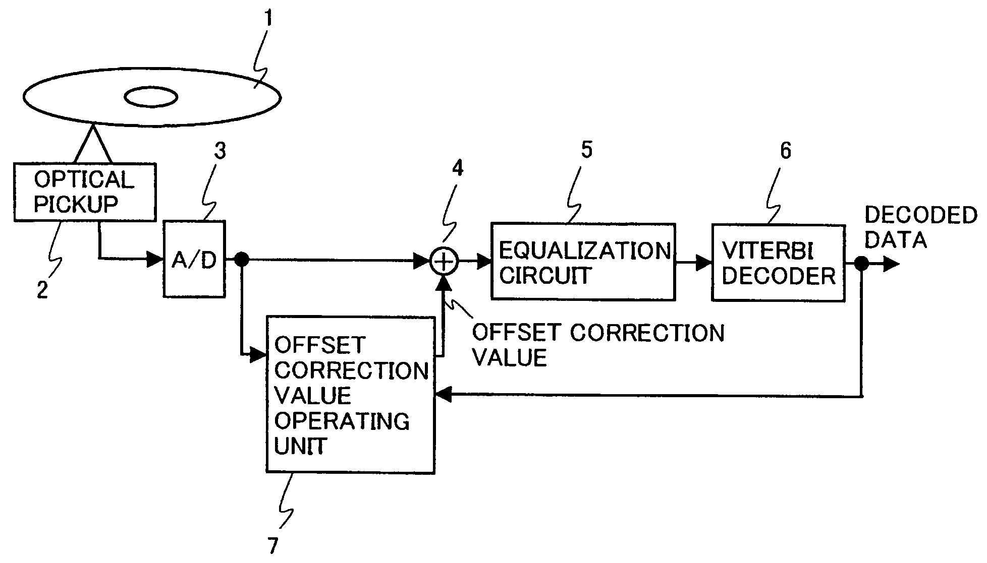
[0050]FIG. 1 is a block diagram showing a configuration of an apparatus for correcting offset according to the present embodiment. In FIG. 1, data recorded on an optical disc 1 is converted to an electrical signal by an optical pickup 2 and input to an AD converter 3. AD converter 3 quantizes a reproduction signal for each clock in synchronization with a bit period of the reproduction signal, and the signal is sequentially output for each clock as a quantized data column. Namely, a block provided subsequently to AD converter 3 serves as a digital circuit operating for each clock. Offset of an output of AD converter 3, that is, the quantized data column is corrected by an adder 4 for adjusting direct-current offset, and a frequency property thereof is corrected by an equalization circuit 5. The output of AD converter 3 is then input to a Viterbi decoder and subject...

second embodiment

[0121

[0122]In the following, a second embodiment of the present invention will be described with reference to the figures. Though the second embodiment is substantially the same as the first embodiment as shown in FIG. 4, it is characterized in that a high pass filter 8 is provided in a preceding stage of offset correction value operating unit 7 and adder 4 for offset correction.

[0123]The reproduction signal of the optical disc contains considerable noise of low frequency caused by reflectivity fluctuation, sensitivity variation of the recording medium, or the like. Since such low-frequency noise tends to cause a decode error, it is desirable to remove the noise as much as possible with a high pass filter.

[0124]On the other hand, the bandwidth of the low frequency noise exhibits a crossover with a low-frequency component in the recording, code such as (d, k) RLL code+NRZI conversion. Accordingly, if the low frequency is carelessly removed with the high pass filter, an essential “low...


PUM


Abstract

An apparatus for correcting offset includes an optical pickup converting data recorded on an optical disc to an electrical signal; an AD converter quantizing a reproduction signal for each clock in synchronization with a bit period of the reproduction signal and sequentially outputting the signal as a quantized data column for each clock; an adder adding an offset adjustment amount to the quantized data column serving as an input signal; a Viterbi decoder performing Viterbi decoding on the signal after offset adjustment for binarization; and an offset correction value operating unit calculating the offset adjustment amount so that a value obtained by dividing a standard deviation of path metric difference between a survivor path and another path merged into the survivor path in the Viterbi decoder by an average of the path metric difference is minimized.

Description

BACKGROUND OF THE INVENTION[0001]1. Field of the Invention[0002]The present invention relates to a technique to reproduce data on a recording medium, and more particularly to an offset correction technique for appropriately controlling a low frequency signal added to an input signal.[0003]2. Description of the Background Art[0004]In recent years, a disc apparatus with high density and large capacity such as a magnetic disc apparatus or an optical disc apparatus represented by a DVD (Digital Versatile Disc) has actively been studied and developed. Since such a disc apparatus has achieved higher density, a PRML (Partial Response Maximum Likelihood) detecting scheme has become indispensable as a signal processing technique for improving an error rate of reproduced data. It is well-known that this scheme combining partial response waveform equalization with maximum likelihood detection considers the frequency property from a disc to an input of a maximum likelihood detector as a “coder”...

Claims


Application Information

Patent Timeline
IPC IPC(8): H03M13/03G11B20/14G11B20/10G11B20/18H03M13/41
CPCG11B20/10009G11B20/10101H03M13/41H03M13/3738G11B20/18G11B2020/1863G11B20/10
Inventor FUJIWARA, TSUNEO
Owner SHARP KK
Why Eureka
Try Eureka