Rare earth element permanent magnet material

a permanent magnet material and rare earth technology, applied in the field of rare earth permanent magnet materials, can solve the problems of difficult to achieve the improvement of magnetic characteristics

Inactive Publication Date: 2007-02-13
MITSUBISHI ELECTRIC CORP
View PDF15 Cites 43 Cited by
  • Summary
  • Abstract
  • Description
  • Claims
  • Application Information

AI Technical Summary

Problems solved by technology

Accordingly, practical improvement of the magnetic characteristics has been difficult to achieve.

Method used


Image

  • Rare earth element permanent magnet material
  • Rare earth element permanent magnet material
  • Rare earth element permanent magnet material

Examples


example 4

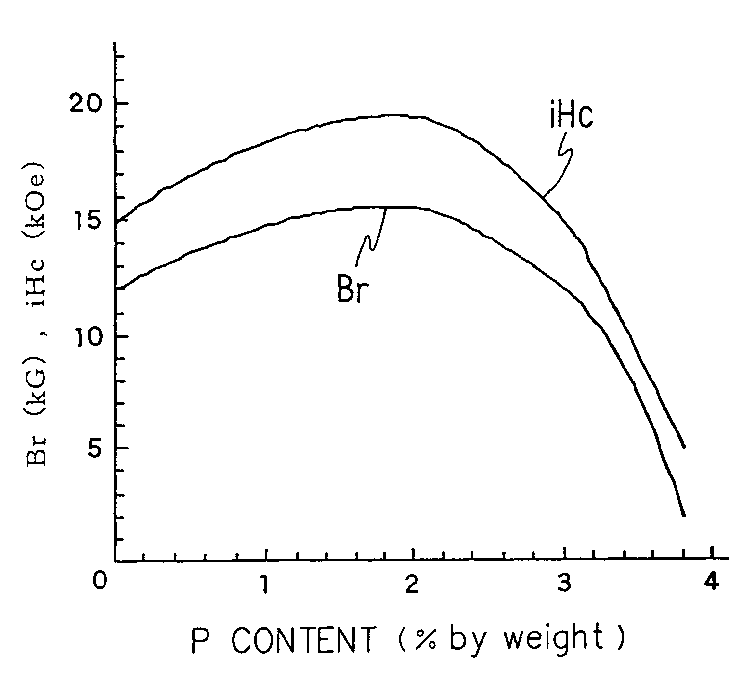
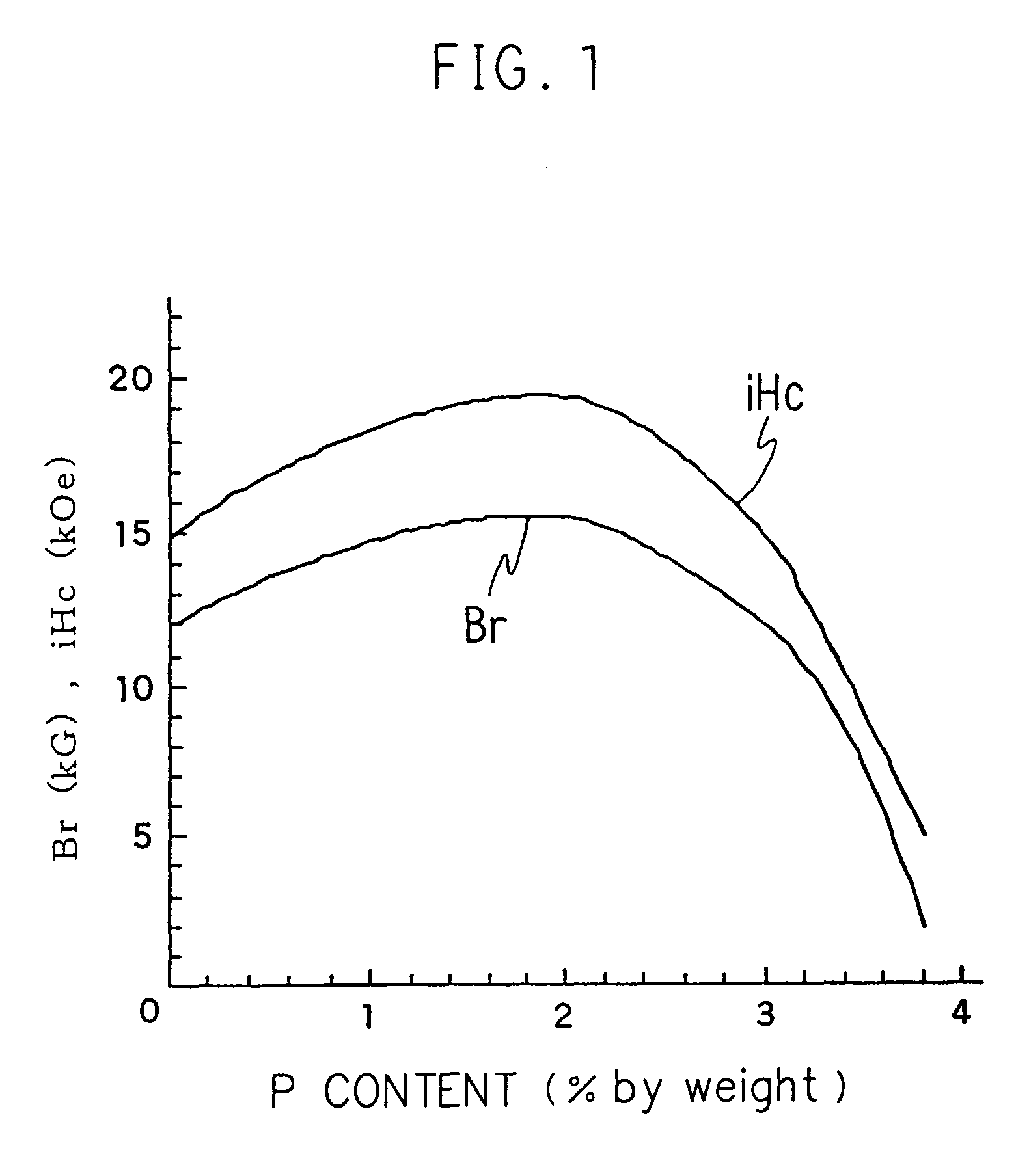
[0038]Nd, Dy, electrolytic iron, Co, ferroboron, iron phosphide and Cu are utilized as starting materials. Then, these materials are mixed into a composition of 30Nd-1Dy-62.8Fe-3Co-1B-0.2Cu-2P according to weight percent (% by weight) in accordance with the same method as in Example 1 and, thereby, a material for a rare earth permanent magnet is prepared.

[0039]The Curie temperature (Tc), the magnetic coercive force (iHc) and the residual magnetic flux density (Br) in this material for a rare earth permanent magnet are measured and the Curie temperature is 450° C., the magnetic coercive force is 16.2 kG and the residual magnetic flux density is 20.3 kOe and, therefore, a great increase in the magnetic characteristics is achieved.

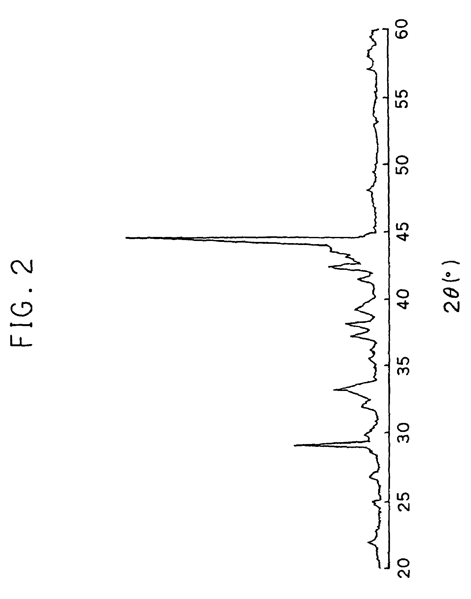
[0040]In addition, it is confirmed that the diffraction graph shows the main phase having a Nd2Fe14B-type tetragonal crystal structure as a result of X-ray diffraction carried out on the crystal structure of the obtained sample using a CuK α-ray.


PUM

PropertyMeasurementUnit
Tcaaaaaaaaaa
Tcaaaaaaaaaa
diameteraaaaaaaaaa

Abstract

A material for a rare earth permanent magnet having a high magnetic coercive force and a high residual magnetic flux density. 28 to 35% by weight of at least one rare earth element selected from the group consisting of neodymium, praseodymium, dysprosium, terbium, and holmium, 0.9 to 1.3% by weight of boron, 0.25 to 3% by weight of phosphorus, iron, and inevitable impurities. It can further comprise 0.1 to 3.6% by weight of cobalt and 0.02 to 0.25% by weight of copper.

Description

TECHNICAL FIELD[0001]The present invention relates to a material for a rare earth permanent magnet having significantly improved magnetic characteristics.BACKGROUND ART[0002]Rare earth permanent magnets have been widely used in the field of electrical and electronic apparatus utilizing their excellent magnetic characteristics and also from economical reasons, and in recent years further improvement in their performance has been required. In an R—Fe—B rare earth permanent magnet, from among rare earth permanent magnets, Nd, which is a primary element, exists in greater abundance than Sm and a great amount of Co is not utilized so that material costs are lessened while the magnetic characteristics far exceed those of rare earth cobalt magnets and an R—Fe—B rare earth permanent magnet is therefore an excellent permanent magnet.[0003]Previously, a variety of attempts have been made to improve the magnetic characteristics of such an R—Fe—B rare earth permanent magnet. Concretely, an exam...

Claims


Application Information

Patent Timeline
Patent Type & Authority Patents(United States)
IPC IPC(8): H01F1/057C22C38/00C22C38/10C22C38/16H01F1/059
CPCC22C38/001C22C38/002C22C38/005H01F1/059C22C38/16H01F1/057H01F1/0577C22C38/10
Inventor NOBUTOKI, HIDEHARUNAGAE, SUGURUHAYASI, SATORU
Owner MITSUBISHI ELECTRIC CORP
Why Eureka
Try Eureka