
Method and device for welding an aluminum-based stud

Inactive Publication Date: 2007-02-13
NEWFREY
View PDF17 Cites 13 Cited by
  • Summary
  • Abstract
  • Description
  • Claims
  • Application Information

AI Technical Summary

Benefits of technology

[0003]Technologies have already been developed to weld T studs to vehicle bodies and frames when the bodies and the T studs are made from iron-based metals. In these welding technologies, the T stud is welded to the body or frame while maintaining a constant level of strength. For example, when the iron-based T stud 1 in FIG. 1 has a 5-mm diameter head 2 and a 3-mm long, 3-mm diameter rod-shaped shaft 3, the height of the stud 1 below the neck after being welded to a base material 5 such as an iron-based body is about 2.6 mm, the reinforcing height (h) of the reinforcement 6 is less than 1 mm, and the diameter (d) of the reinforcement 6 is less than 5 mm. In this way, enough space remains on the shaft 3 of the molten T stud 1 to accommodate the clip disclosed in Japanese Utility Model Application Disclosure No. 63-173583, and attach the clip properly and securely.
[0008]Still another aspect of the present invention includes a welding method, wherein an aluminum or aluminum alloy stud is brought into contact with an aluminum or aluminum alloy base material, voltage is applied between the stud and the base material, the stud is lifted slightly off the base material, an arc is generated, the tip of the stud and the section of the base material to be melted are melted, pressure is applied to the tip of the stud and the section of the base material that has been melted and the stud and base material are welded together, the current is divided into at least three stages and incrementally increased from the beginning to the end while the main arc is generated, and / or the molten tip of the aluminum or aluminum alloy stud is applied under pressure to the molten base material in under five milliseconds after the arc current has been cut off. As a result, an aluminum-based stud can be welded properly.
[0009]Similarly, in still a further aspect of the present invention, a welding device or system is used wherein an aluminum or aluminum alloy stud is brought into contact with an aluminum or aluminum alloy base material, voltage is applied between the stud and the base material, the stud is lifted slightly off the base material, an arc is generated, the tip of the stud and the section of the base material to be melted are melted, pressure is applied to the tip of the stud and the section of the base material that has been melted and the stud and base material are welded together, the current is divided into stages and incrementally increased from beginning to end as the arc is generated, and / or the molten tip of the aluminum or aluminum alloy stud is applied under pressure to the molten base material in under five milliseconds after the main arc current has been cut off. As a result, an aluminum-based stud can be welded properly.

Problems solved by technology

When the base material of the body or frame consists of an aluminum-based metal such as aluminum or an aluminum alloy, it is difficult to weld an iron-based T stud to it.
If a stud consisting of an aluminum-based metal such as aluminum or an aluminum alloy is welded in the same manner as an iron-based stud, the proper height below the neck, reinforcing height, and welding spot diameter cannot be reliably obtained.
In addition, the strength after welding varies and a stable welding strength cannot be obtained.

Method used


Image

  • Method and device for welding an aluminum-based stud
  • Method and device for welding an aluminum-based stud
  • Method and device for welding an aluminum-based stud

Examples


Embodiment Construction

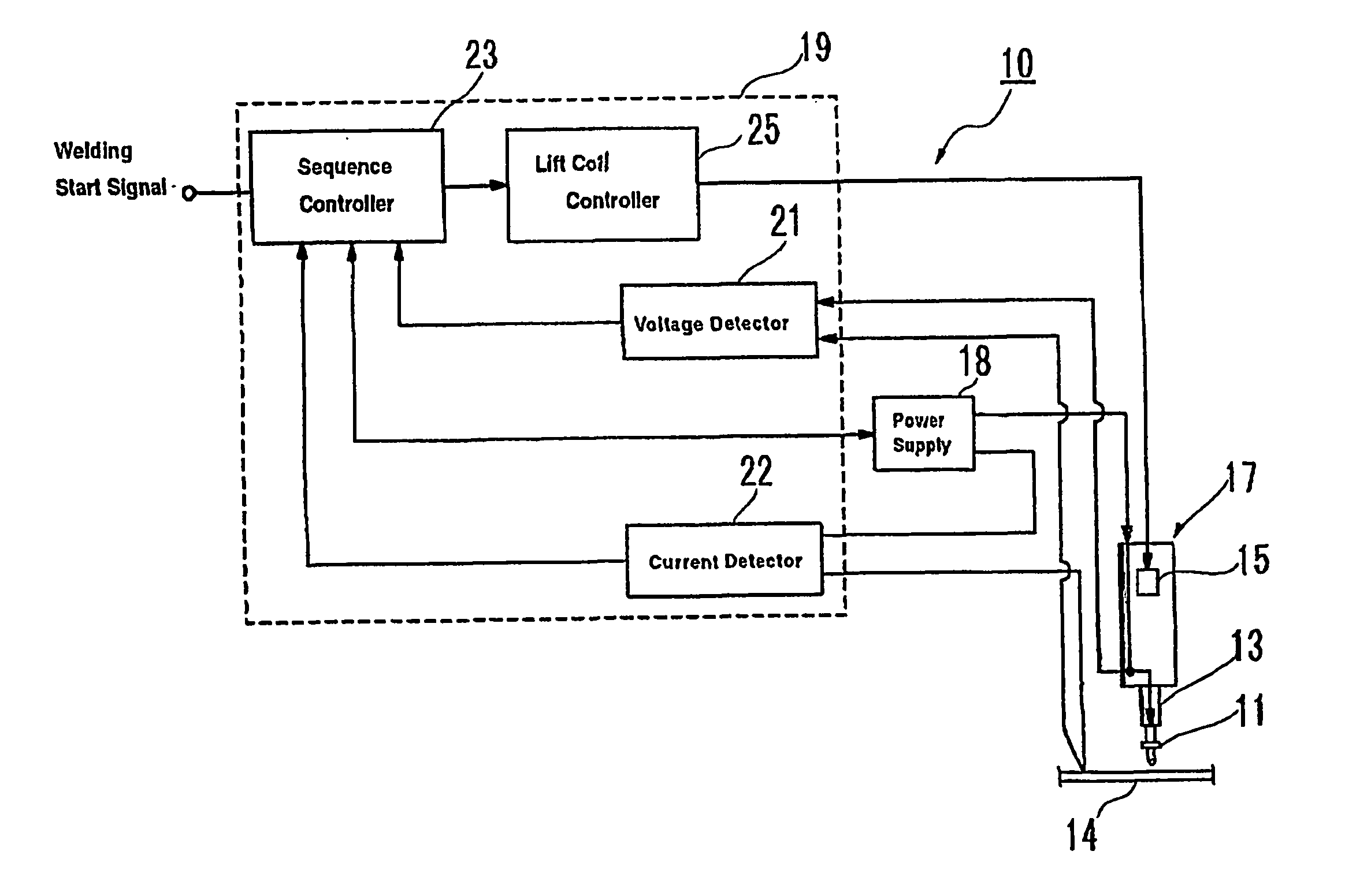
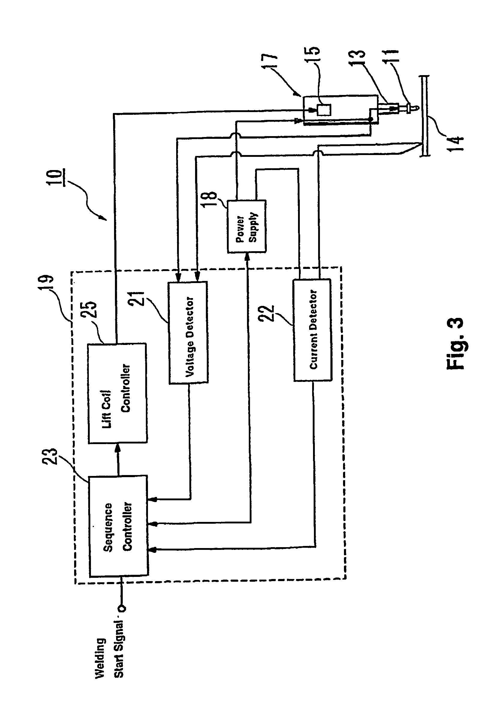
[0017]The following is an explanation of working examples of the present invention with reference to the drawings. FIG. 3 is a block diagram of the circuit in a welding device 10 for welding an aluminum or aluminum alloy stud to an aluminum or aluminum alloy base material. The stud welding device 10 contains a collet 13 for holding a stud 11 at the tip, a welding gun 17 with a lift coil 15 as the lifting means for lifting the stud 11 held by the collet 13 off the base material 14, and a power source 18 connected to the welding gun to supply a specific amount of power between the stud 11 and the base material 14. It is not necessary, but the stud can also be welded in an inactive gas atmosphere such as an argon gas atmosphere. A stud-surrounding member such as a ferrule (not shown) can be installed on the collet 13 holding the stud.

[0018]A control device 19 is connected to the power source 18 and the welding gun 17. The stud welding device 10 is a so-called drawn-arc stud welding dev...


PUM

PropertyMeasurementUnit
Timeaaaaaaaaaa
Timeaaaaaaaaaa
Timeaaaaaaaaaa

Abstract

A method of welding a stud (11) is provided. In another aspect of the present invention, a welding system is provided for a weld stud (11). A further aspect of the present invention employs a weld stud (11) with a substantially conical end section (29). Still another aspect of the present invention includes a welding method, wherein an aluminum or aluminum alloy stud (11) is brought into contact with an aluminum or aluminum alloy base material (14), voltage is applied between the stud (11) and the base material (14), the stud (11) is lifted slightly off the base material (14), an arc is generated, the tip of the stud (11) and the section of the base material (14) to be melted are melted, pressure is applied to the tip of the stud (11) and the section of the base material (14) that has been melted and the stud (11) and base material (14) are welded together, the current is divided into at least three stages and incrementally increased from the beginning to the end while the main arc is generated, and / or the molten tip of the aluminum or aluminum alloy stud (11) is applied under pressure to the molten base material (14) in under five milliseconds after the arc current has been cut off.

Description

BACKGROUND AND SUMMARY OF THE INVENTION[0001]The present invention relates to a method and device for welding an aluminum or aluminum alloy stud and, more specifically, to a welding method and device in which a stud is brought into contact with a base material, voltage is applied between the stud and the base material, the stud is lifted slightly off the base material, an arc is generated between the stud and the base material, the tip of the stud and the section of the base material to be melted are melted, pressure is applied to the tip of the stud and the section of the base material that has been melted, and the stud and base material are welded together after the current has been cut off.[0002]In a well known method, a stud is brought into contact with a base material, voltage is applied between the stud and the base material, the stud is lifted slightly off the base material, an arc is generated between the stud and the base material, the tip of the stud and the section of the...

Claims


Application Information

Patent Timeline
IPC IPC(8): B23K9/20B23K35/02
CPCB23K9/201B23K9/205B23K35/0288B23K9/207B23K2203/10B23K2103/10
Inventor SAKODA, KANJI
Owner NEWFREY
Features
  • Generate Ideas
  • Intellectual Property
  • Life Sciences
  • Materials
  • Tech Scout
  • Unparalleled Data Quality
  • Higher Quality Content
  • 60% Fewer Hallucinations
Learn More