Machine for machining workpieces, especially crankshafts and camshafts, with at least one internal cutter milling tool

a technology for crankshafts and camshafts, which is applied in the direction of maintaining and safety accessories, large fixed members, turning apparatuses, etc., can solve the problems of increasing temperature constancy, and achieve high bending and bending stiffness results, high machining precision, and high stiffness

Active Publication Date: 2007-02-20
GEBR HELLER MASCHFAB GMBH
View PDF22 Cites 10 Cited by
  • Summary
  • Abstract
  • Description
  • Claims
  • Application Information

AI Technical Summary

Benefits of technology

[0006]It is an object of the invention to configure the machine of the aforementioned kind such that the workpieces can be machined at high machining precision in a simple and proper way even though the machine has a compact configuration.
[0008]In the machine according to the invention, the tool is secured on the slide part of the compound slide. It is moved along the correlated guide system while the slide part with the tool is movable transversely to this guide system. Advantageously, the machine according to the invention has two headstocks and optionally steady rests. For the tool side as well as the workpiece side of the machine, the two parallel guide systems are provided that extend in the Z direction. One of the guide systems is provided for the compound slide having the slide part while the other guide system is correlated with the headstocks as well as, optionally, the steady rest. The tool can be moved by means of the slide part transversely to the workpiece axis. The workpieces to be machined, especially, crankshafts and camshafts, are clamped within the chucks so as to be rotationally movable (axis C). Producing the circular-cylindrical bearing locations is realized by axis interpolation between the slide part and the C axis. By means of the separate guide systems for the compound slide and the headstocks / steady rests, respectively, the guide base of each individual component assembly can be sized to be sufficiently large so that a high twisting and bending stiffness results. Because of the separate guide systems, the headstocks in the machine according to the invention can be configured with minimal chuck projection so that the workpiece can be clamped with very high stiffness. This configuration of the compound slide and of the head-stocks / steady rests results in very high machining precision. Moreover, the vibration and chatter tendencies are reduced. This results in advantages such as higher machining precision, higher process safety, long tool service life, and higher cutting output etc.
[0009]As a result of the separate guide systems, it is advantageously possible to provide guide path covers that prevent reliably the penetration of cuttings but still have a simple configuration. The wear of guide path strippers is greatly reduced and the guide paths themselves are no longer exposed to the cuttings that strike at high velocity. In this way, the reliability and thus the machine availability is increased. Moreover, temperature constancy is increased because the cuttings can no longer heat the guide paths. In the case of mass production, it is therefore possible to provide a high machining reliability. Because of the guide path covers, it is now also possible to use roller bearing supported guide systems. In comparison to slide bearings, roller bearings are sensitive with regard to penetration of particles such as cuttings; however, they have several advantages. They can be simply and quickly mounted, have a reduced slide resistance, and enable high quick traverse speeds while causing minimal heating. In comparison to a sliding guide action, no stick-slip effect occurs. The precision is very high because of the pretension of the bearing. Moreover, as a result of the arrangement of the milling unit on a separate guide system, the accessibility of the working space of the machine is significantly improved.

Problems solved by technology

Moreover, temperature constancy is increased because the cuttings can no longer heat the guide paths.

Method used


Image

  • Machine for machining workpieces, especially crankshafts and camshafts, with at least one internal cutter milling tool
  • Machine for machining workpieces, especially crankshafts and camshafts, with at least one internal cutter milling tool
  • Machine for machining workpieces, especially crankshafts and camshafts, with at least one internal cutter milling tool

Examples


Embodiment Construction

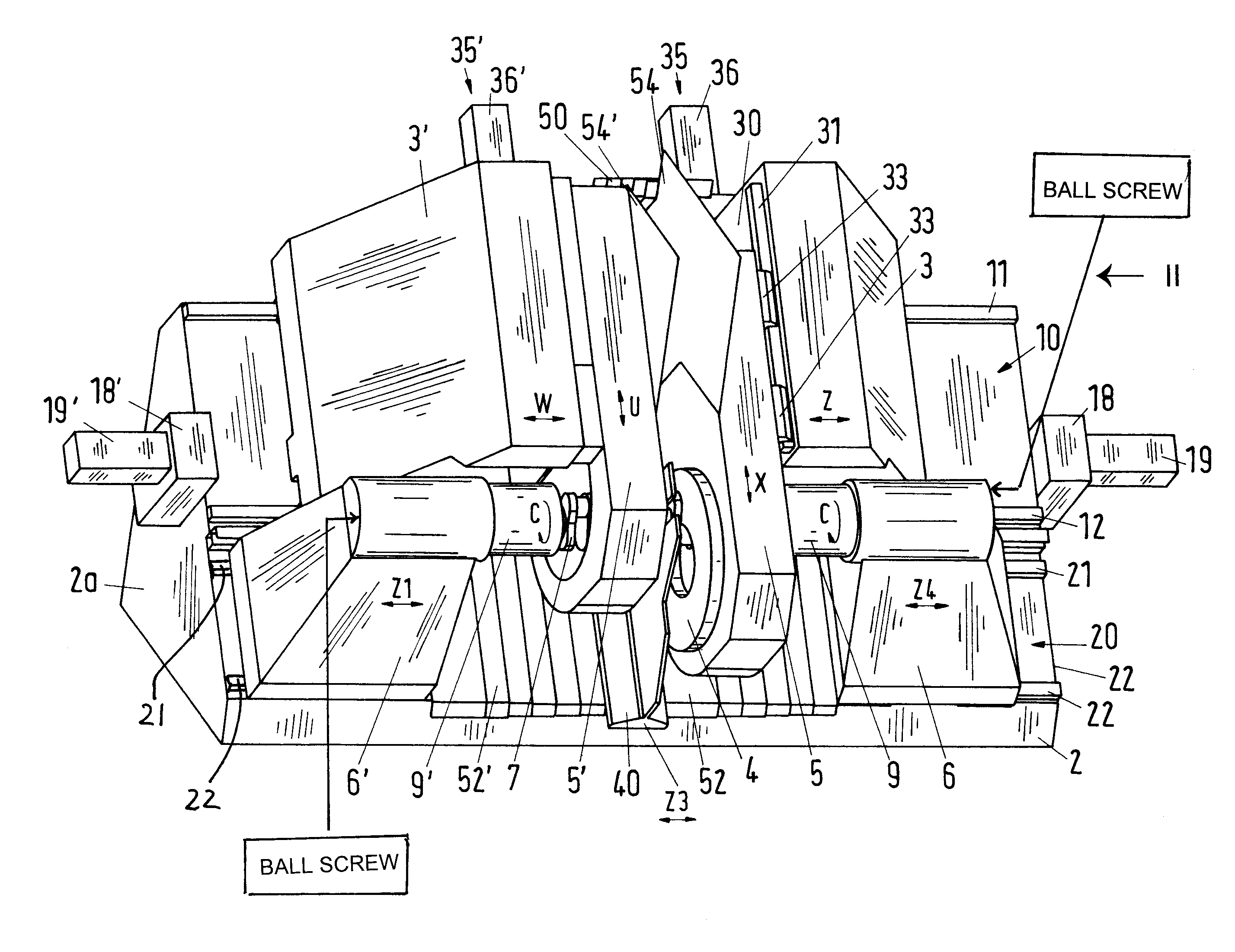
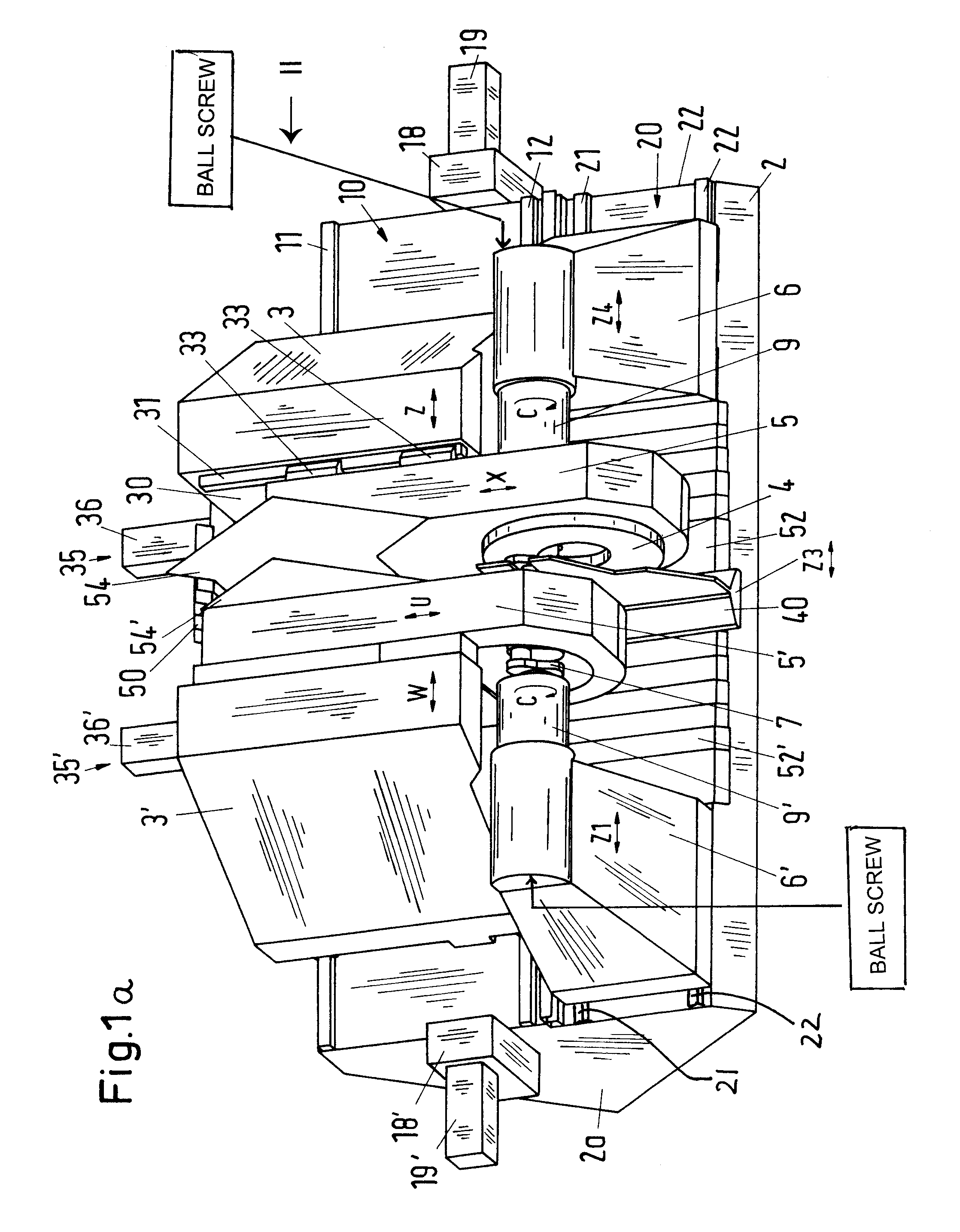
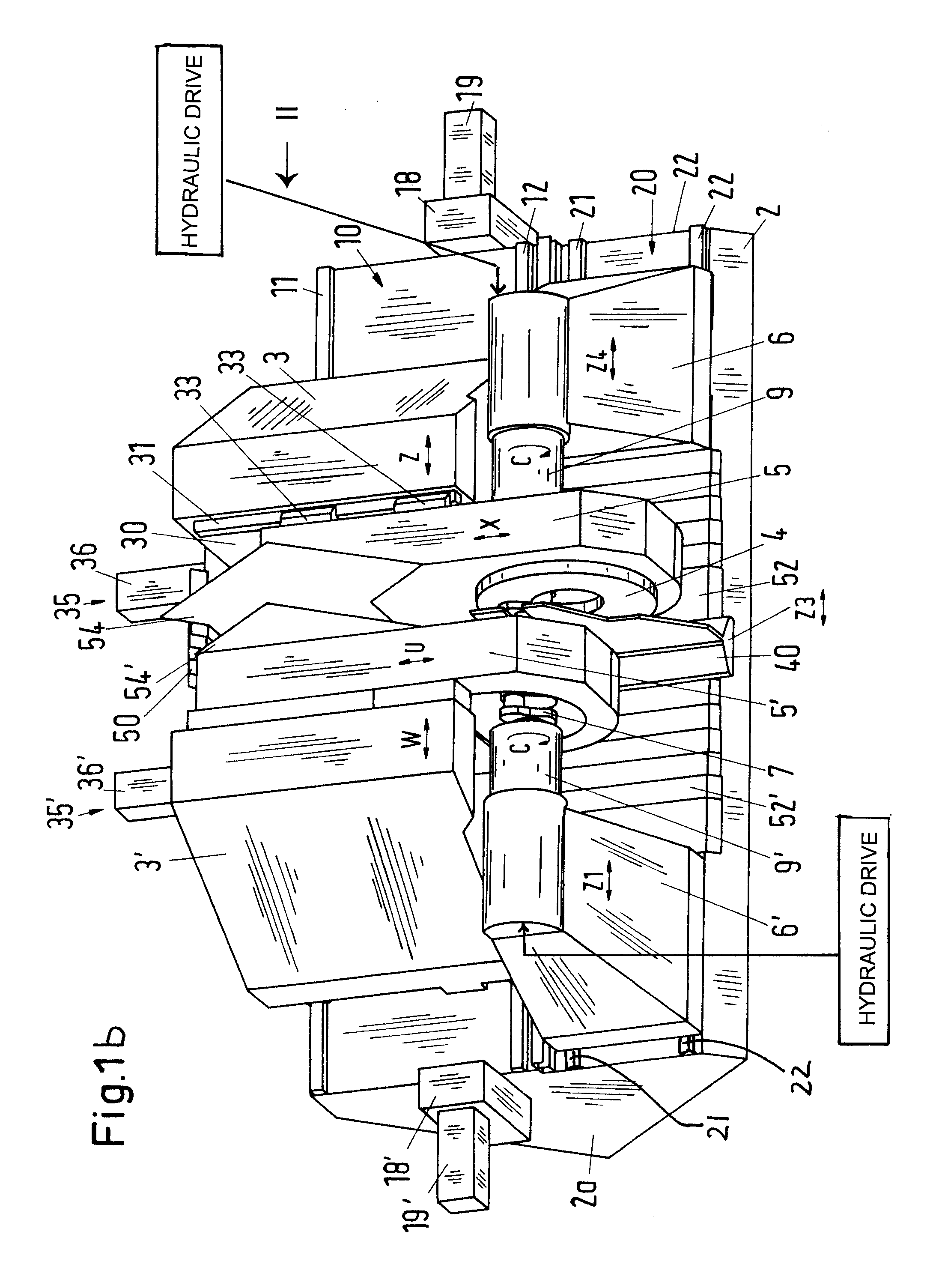
[0017]The machine tool with internal cutter for milling workpieces comprises a machine frame 2 that is provided with an inclined contact side 1 (FIG. 2). On the machine frame 2, two compound slides 3, 3′ are movably supported. They are positioned opposite one another at a spacing at the same level. The two compound slides 3, 3′ each support a slide part in the form of a milling unit 5, 5′. In the area adjacent to the compound slides 3, 3′, two headstocks 6, 6′ are provided on the machine frame 2 for clamping the workpiece 7 to be machined. Also provided is a steady rest 40 that is located in the area between the headstocks 6, 6′ and supports, as is known in the art, the workpiece 7 during machining. The machine frame 2 is of an inclined bed configuration and can be made of steel, can be cast, or made as a concrete structure. On the inclined side 1, a guide system 10 is provided in the upper area that can be a sliding guide but is preferably configured as a roller bearing guide. The ...


PUM

PropertyMeasurementUnit
axis of rotationaaaaaaaaaa
areaaaaaaaaaaa
energyaaaaaaaaaa

Abstract

A machine for machining workpieces has at least one milling tool with an internal cutter. The machine is provided with a first guide system and a second guide system parallel to the first guide system. The first guide system has at least one compound slide having a slide part, wherein the at least one compound slide is moveable in a longitudinal direction of the first guide system and wherein the slide part is moveable transversely to the longitudinal direction. A milling tool is secured on the slide part. The first and second guide systems have sliding guides or roller bearing guides. The at least one compound slide has a transverse guide system and the slide part is guided on the transverse guide system.

Description

BACKGROUND OF INVENTION[0001]The invention relates to a machine for machining workpieces, especially crankshafts and camshafts, comprising at least one milling tool with internal cutter and two parallel guide systems.[0002]The machining of crankshafts poses great requirements on the processing machines, on the tools, and cutting materials as well as the processing method. The crankshafts, because of their length and their complicated shape, are very instable. However, different surfaces of the crankshaft must be machined with high precision. The machining forces that occur during milling deform the workpiece, and this causes dimensional inaccuracy.[0003]The machining of crankshafts is carried out, for example, on milling machines with internal cutter. The circular-cylindrical mains located on the workpiece axis are machined and, if needed, also the adjoining web surfaces, as well as the circular-cylindrical pins that are eccentric to the axis of the workpiece. U.S. Pat. No. 4,171,65...

Claims


Application Information

Patent Timeline
Patent Type & Authority Patents(United States)
IPC IPC(8): B23C3/06B23P23/00B23C3/08
CPCB23C3/06B23C3/08Y10T409/307616B23C2220/68Y10T409/307784Y10T82/2566Y10T82/2597Y10T82/19Y10T409/305656Y10T409/308344Y10T29/5109Y10T409/309576Y10T29/17Y10T409/30392Y10T409/305712
Inventor HEMMING, CHRISTOPHMARKER, WOLFGANGBONFERT, HEINRICH
Owner GEBR HELLER MASCHFAB GMBH
Why Eureka
Try Eureka