Flexible heart valve

a heart valve and flexible technology, applied in the field of medical devices, can solve the problems of occluded natural orifice area, tissue leaflet area along the wireform is especially susceptible to calcification, and calcification, and achieve the effect of reducing stress concentration in the valve leaflet and facilitating valve assembly and implantation procedures

Inactive Publication Date: 2007-02-20
EDWARDS LIFESCIENCES CORP
View PDF52 Cites 33 Cited by
  • Summary
  • Abstract
  • Description
  • Claims
  • Application Information

AI Technical Summary

Benefits of technology

[0008]This invention details a partially stented valve design. The stent is to be completed by the natural aortic root when the valve is implanted. The final valve conforms to the movement of the natural aortic root and therefore provides a larger orifice area like a stentless valve. The valve, however, includes a stent structure that will facilitate the valve assembly and implantation procedures. The movement of the stent structure and leaflet shape also helps to reduce stress concentration in the valve leaflet.

Problems solved by technology

However, the tissue material tends to calcify after the long term implantation.
That is, calcium compound accumulates in the tissue leaflets, eventually making them stiff.
The tissue leaflet area along the wireform is especially susceptible to the calcification because of the high bending stresses imposed at that interface.
Although this type of valve has been proven effective, some researchers assert that it excessively occludes the natural orifice area, and thus reduces potential blood flow therethrough.
Although stentless valves generally provide greater orifice area, they do not have the advantage of the reliable leaflet support structure of stented valves.
Moreover, a stentless valve is more difficult to make, and the implantation of such a device requires much more skill and experience of the cardiac surgeon.
Only a few heart centers in the United States are able to perform such a procedure and thus the use of stentless valves is restricted.
However, the stent structure appears to be relatively complex, with numerous interior surfaces, thus raising concerns of thromboembolisms and even component failure.

Method used


Image

  • Flexible heart valve
  • Flexible heart valve
  • Flexible heart valve

Examples


Embodiment Construction

[0032]The following detailed description, and the figures to which it refers, are provided for the purpose of describing examples and specific embodiments of the invention only and are not intended to exhaustively describe all possible examples and embodiments of the invention. Identical elements and features are given the same reference number as appropriate for purposes of describing the various embodiments of the present invention.

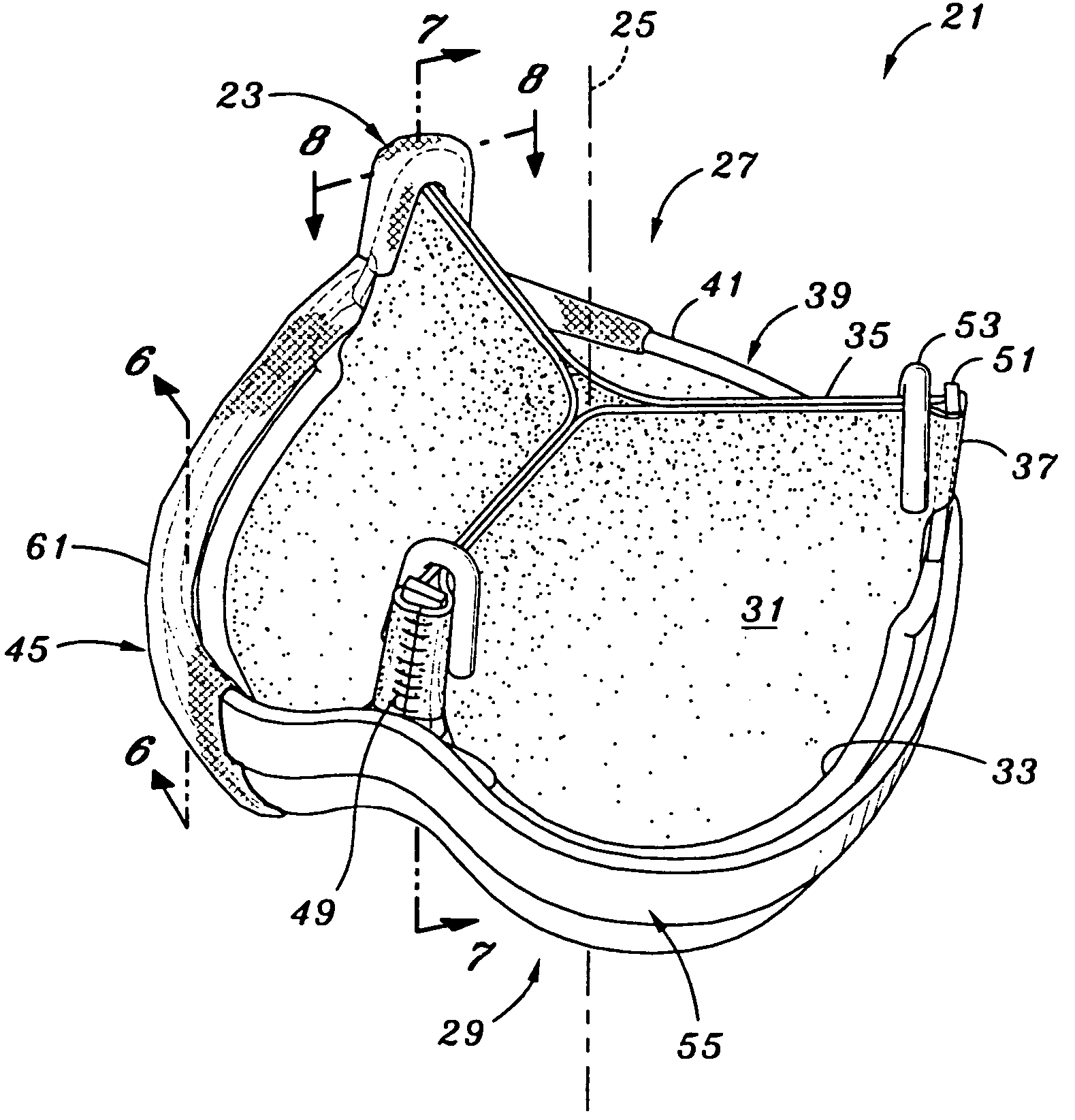
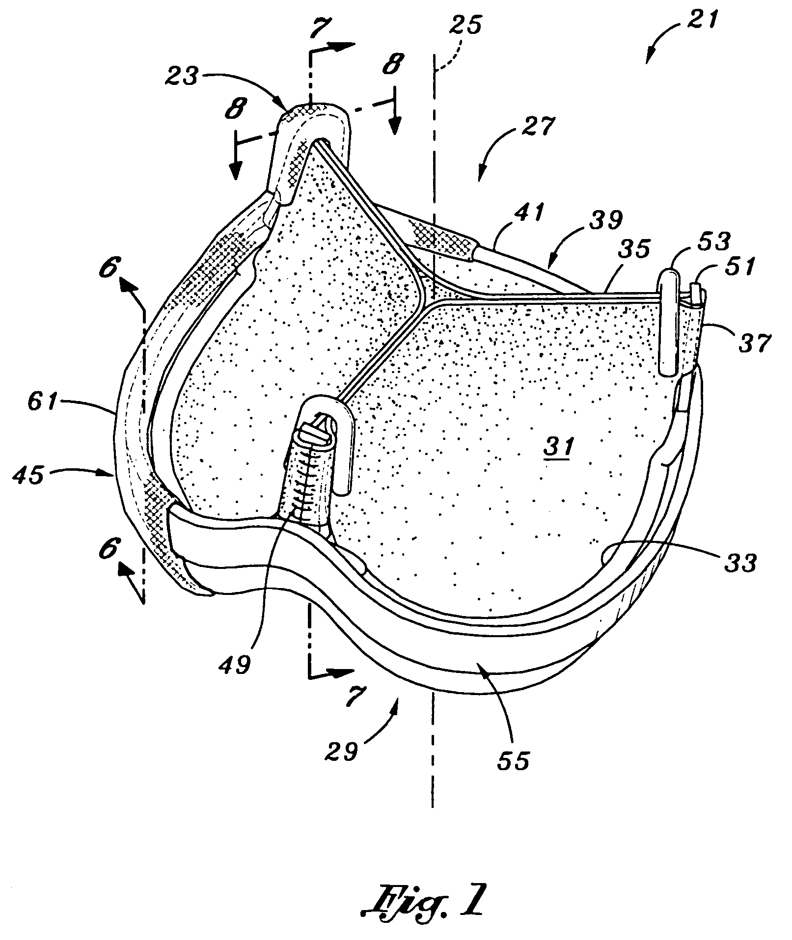
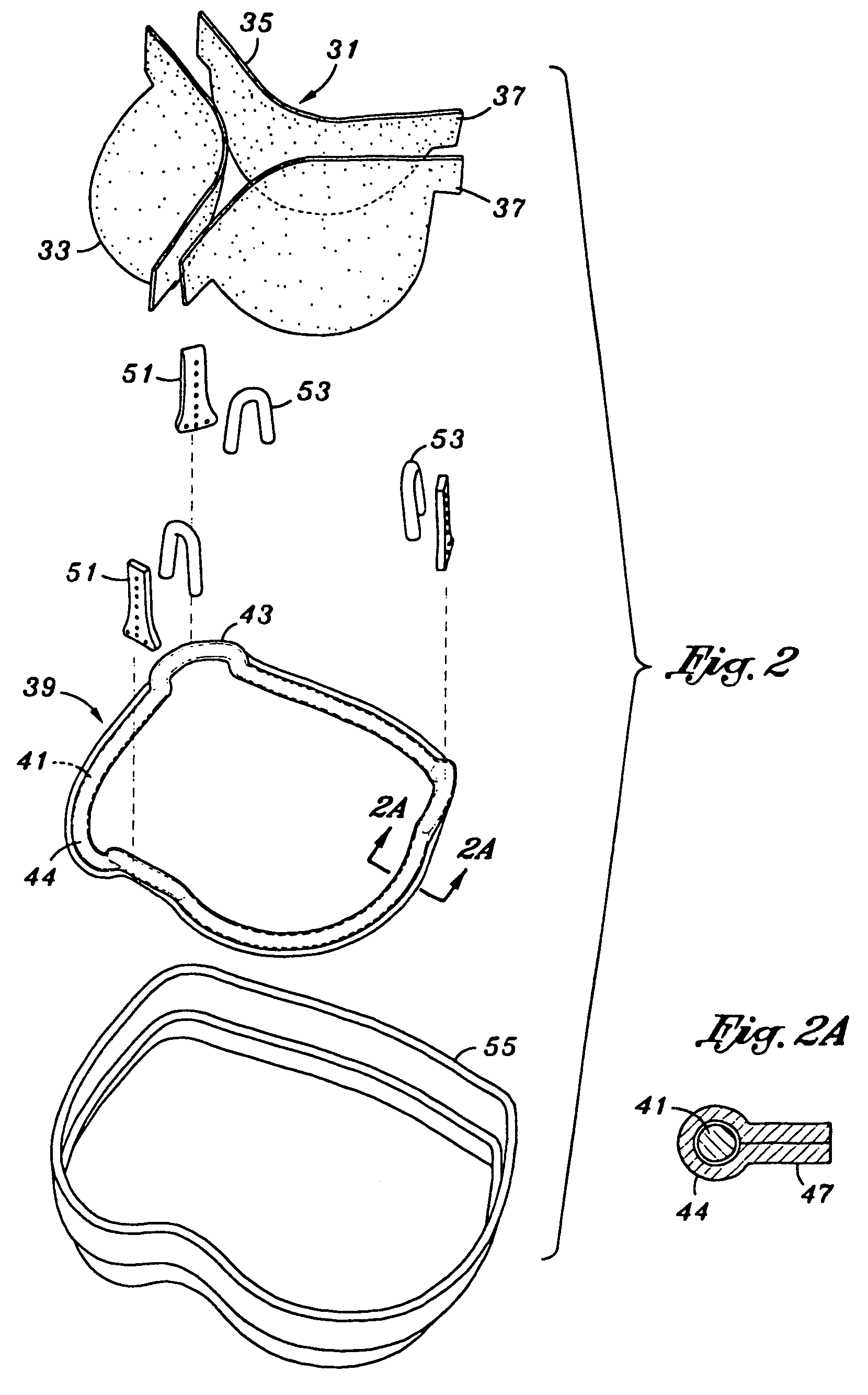
[0033]Referring now to FIGS. 1 and 2, a replacement tissue type heart valve 21 of the present invention for implantation in an annulus of a heart is constructed about a valve axis 25 that defines an outflow end 27 and an inflow end 29. The valve includes commissures 23 directed to the outflow end and adapted to move in conformity with an anatomical wall structure adjacent the annulus of the heart. Although the valve 21 of the present invention is particularly suitable for implantation at the aortic valve position, it may also function adequately in othe...


PUM


Abstract

A flexible prosthetic tissue-type heart valve having commissures that are substantially decoupled from a cusp support structure. The valve includes three leaflets having arcuate cusp edges and opposed concave shaped free edges, with outwardly-directed attachment tabs therebetween. A cusp support structure in either one or more pieces attaches to the leaflet cusp edges. Three commissures are each formed partly with an axially-extending insert member to which two adjacent leaflet tabs attach. An inverted V-shaped clip maintains close contact between the adjacent leaflet tabs and provides a stress-relieving clamping action in conjunction with the insert member. The insert member attaches about its lower end to base sections of the cusp support structure, or to an intermediate sewing ring, so that the commissures may pivot about the cusp support structure.

Description

RELATED APPLICATIONS [0001]The present application is a continuation of application Ser. No. 10 / 245,000, filed on Sep. 17, 2002, now abandoned, which is a divisional of application Ser. No. 09 / 668,660, filed on Sep. 22, 2000, now U.S. Pat. No. 6,641,382 B1.FIELD OF THE INVENTION[0002]The present invention relates generally to medical devices and particularly to flexible tissue-type heart valve prostheses designed to attach along the valve annulus and adjacent anatomical wall structure.BACKGROUND OF THE INVENTION[0003]Prosthetic heart valves are used to replace damaged or diseased heart valves. In vertebrate animals, the heart is a hollow muscular organ having four pumping chambers: the left and right atria and the left and right ventricles, each provided with its own one-way valve. The natural heart valves are identified as the aortic, mitral (or bicuspid), tricuspid and pulmonary valves. Prosthetic heart valves can be used to replace any of these naturally occurring valves, althoug...

Claims


Application Information

Patent Timeline
Patent Type & Authority Patents(United States)
IPC IPC(8): A61F2/06A61F2/24
CPCA61F2/2409A61F2/2418A61F2/2412A61F2220/0075
Inventor CAO, DONGBU
Owner EDWARDS LIFESCIENCES CORP
Why Eureka
Try Eureka