Osteogenic fusion device

a fusion device and osteogenic technology, applied in the field of implants, can solve the problems of affecting the normal anatomical function of the disc, affecting and the hardware used to maintain the stability of the spine became superfluous, so as to reduce the chance of neurological complications or damag

Inactive Publication Date: 2007-02-20
WARSAW ORTHOPEDIC INC
View PDF54 Cites 107 Cited by
  • Summary
  • Abstract
  • Description
  • Claims
  • Application Information

AI Technical Summary

Benefits of technology

[0019]It is one object of the present invention to provide an interbody fusion device that allows the greatest possible contact between the adjacent vertebrae and the bone growth-inducing material supported by the osteogenic fusion device. It is a further object to provide such a osteogenic fusion device that is capable of supporting the loads generated throughout the spine without stress-shielding developing bone within the osteogenic fusion device.
[0020]Another object of the invention is achieved by features that minimize the radiopacity of the device. This results in a benefit to the surgeon of being able to more readily assess the progress of a spinal fusion.
[0021]Yet another object of the invention is to provide an interbody fusion device whereby enough lateral exposure is present to place two large devices side-by-side to distract the disc space and facilitate fusion.
[0023]Yet a further object of the invention is to provide an implant system which is placed in the intervertebral space with minimal retraction of the spinal cord to lessen the chance of neurological complications or damage.

Problems solved by technology

In many cases, these pathologies affecting the spinal disc can disrupt the normal anatomical function of the disc.
In the early history of these osteogenic fusion devices, the osteogenic fusion devices were fanned of cortical-cancellous bone which was not strong enough to support the weight of the spinal column at the instrumented level.
With this technique, once fusion occurred across and incorporating the bone osteogenic fusion device, the hardware used to maintain the stability of the spine became superfluous.
Nevertheless, some of the interbody fusion devices still have difficulty in achieving a complete fusion, at least without the aid of some additional stabilizing device, such as a rod or plate.
Moreover, some of the devices are not structurally strong enough to support the heavy loads and bending moments applied at certain levels of the spine, namely those in the lumbar spine.
Even with devices that do not have these difficulties, other less desirable characteristics exist.
The stress-shielding phenomenon relieves some or all of the load applied to the material to be fused, which can greatly increase the time for complete bone growth, or disturb the quality and density of the ultimately formed fusion mass.
A further difficulty encountered with many fusion implants is that the material of the implant is not radiolucent.
Since most fusion devices completely surround and contain the bone graft material housed within the cage, the developing fusion mass within the metal cage between the adjacent vertebrae cannot be seen under traditional radiographic visualizing techniques and only with the presence of image scatter with CT scans.
Thus, the spinal surgeon does not have a means to determine the progress of the fusion, and in some cases cannot ascertain whether the fusion was complete and successful.

Method used


Image

  • Osteogenic fusion device
  • Osteogenic fusion device
  • Osteogenic fusion device

Examples


Embodiment Construction

[0069]For the purposes of promoting an understanding of the principles of the invention, reference will now be made to the embodiments illustrated in the drawings and specific language will be used to describe the same. It will nevertheless be understood that no limitation of the scope of the invention is thereby intended, such alterations and further modifications in the illustrated device, and such further applications of the principles of the invention as illustrated therein being contemplated as would normally occur to one skilled in the art to which the invention relates.

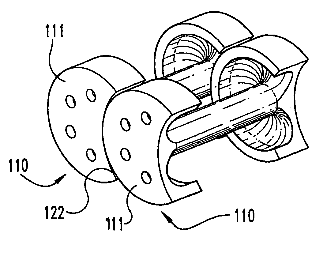
[0070]The present invention contemplates osteogenic fusion devices for use as interbody fusion devices. The osteogenic fusion devices include opposite end pieces that are configured to span the intervertebral disc space and engage the adjacent vertebral bodies. The inventive osteogenic fusion devices include a central element separating the two end pieces and substantially spanning the anterior-posterior length...


PUM

PropertyMeasurementUnit
dimensionaaaaaaaaaa
outer diameteraaaaaaaaaa
concave shapeaaaaaaaaaa

Abstract

An interbody osteogenic fusion device is provided that includes opposite end pieces with an integral central element. The end pieces are sized to maintain the height of an intervertebral disc space. The central element has a much smaller diameter so that the osteogenic fusion device forms an annular pocke around the central element. An osteogenic material is disposed within the annular pocket between the opposite end pieces. In one embodiment,the osteogenic material constitutes a collagen sheet soaked in asolution containing a bone morphogenetic protein. The osteogenic fusion device is configured so that the osteogenic material is in direct contact with the adjacent vertebral bone. In addition to the enhanced area of contact between the vertebral bone and the fusion material, the inventive osteogenic fusion device reduces stress-shielding and minimizes the radiopacity of the implant so that growth of the fusion mass can be continuously assessed. In yet another embodiment, the osteogenic fusion device includes at least one end piece with a truncated surface. The osteogenic fusion devices of the present invention may be combined with other fusion devices to form an implant system. The implant system includes at least one load bearing member having a truncated surface configured to nest within another load bearing member, preferably the load bearing, osteogenic fusion device of the present invention. The invention also provides implant systems comprising adjacent load bearing members connected to one another to resist lateral separation. Methods of promoting fusion bone growth in the space between adjacent vertebrae utilizing devices and systems of the invention are also described.

Description

[0001]This application is a divisional of U.S. patent application Ser. No. 09 / 581,335, now U.S. Pat. No. 6,648,916 filed Sep. 25, 2000, which is the National Stage of International Application No. PCT / US98 / 26254 filed Dec. 10, 1998, published in English, which is a continuation-in-part of U.S. patent application Ser. No. 08 / 988,142 filed Dec. 10, 1997, now U.S. Pat. No. 6,146,420, all of which are hereby incorporated by reference in their entirety.BACKGROUND OF THE INVENTION[0002]The present invention relates to an implant to be placed into the intervertebral space left after the removal of a damaged spinal disc. Specifically, the invention concerns an osteogenic fusion device that enhances arthrodesis or fusion between adjacent vertebrae while also maintaining the normal spinal anatomy at the instrumented vertebral level.[0003]In many cases, low back pain originates from damages or defects in the spinal disc between adjacent vertebrae. The disc can be herniated or can be affected b...

Claims


Application Information

Patent Timeline
Patent Type & Authority Patents(United States)
IPC IPC(8): A61F2/44A61F2/00A61F2/02A61F2/28A61F2/30A61F2/46
CPCA61F2/446A61F2/4611A61F2002/4475A61F2310/00359A61F2002/4623A61F2210/0004A61F2220/0025A61F2220/0041A61F2230/0006A61F2230/0008A61F2230/0013A61F2230/0023A61F2230/0028A61F2230/0047A61F2230/0067A61F2230/0069A61F2230/0091A61F2250/0063A61F2310/00017A61F2310/00023A61F2310/00161A61F2310/00179A61F2310/00365A61L2430/38A61F2/28A61F2/30744A61F2/30767A61F2/442A61F2002/2817A61F2002/2835A61F2002/30062A61F2002/30116A61F2002/30125A61F2002/30131A61F2002/30156A61F2002/30166A61F2002/30169A61F2002/3021A61F2002/30224A61F2002/30225A61F2002/3024A61F2002/30293A61F2002/30329A61F2002/30383A61F2002/304A61F2002/30433A61F2002/30599A61F2002/30611A61F2002/30616A61F2002/30677A61F2002/30774A61F2002/30777A61F2002/30785A61F2002/30787A61F2002/3082A61F2002/3085A61F2002/30874A61F2002/448A61F2/4603A61F2002/30235A61F2002/30593A61F2002/30604A61F2002/30873A61F2/44
Inventor MCKAY, WILLIAM F.
Owner WARSAW ORTHOPEDIC INC
Why Eureka
Try Eureka