
Integrated sprocket and housing and manufacturing method therefor

a technology of integrated sprockets and housings, which is applied in the direction of solid-state diffusion coatings, machines/engines, hoisting equipment, etc., can solve the problems of low friction, difficulty in manufacturing housings, and inability to meet the requirements of strength, accuracy, and low friction at the same time. achieve the effect of low friction

Inactive Publication Date: 2007-02-20
DIAMET CORP
View PDF9 Cites 3 Cited by
  • Summary
  • Abstract
  • Description
  • Claims
  • Application Information

AI Technical Summary

Benefits of technology

[0015]The present invention was conceived in view of the above circumstances, and an object of the present invention is to provide an integrated sprocket and housing which satisfies the requirements such as strength, accuracy, and low friction at the same time.
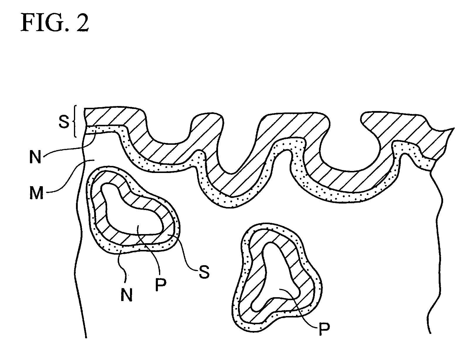
[0018]According to the integrated sprocket and housing of the present invention, because the sprocket portion and the housing portion are integrally formed, the assembling process is simplified. In addition, the nitrided layer, which is formed after pores are filled with the steam oxidized layer, has thickness which is less than that of the steam oxidized layer, the integrated sprocket and housing has preferable low friction performance and strength due to the nitrided layer having an appropriate thickness.
[0020]According to the above integrated sprocket and housing, because the hardened layer is formed only on the surface of the teeth, the integrated sprocket and housing is provided with the teeth having high strength without having deformations in the sliding surface which must have high accuracy in shape. In addition, because the high-frequency induction hardening process, in which the teeth are heated to a temperature exceeding the transition point of the ferrous powder material, is applied only to the teeth in the sprocket portion, the overall shape of the integrated sprocket and housing will not be affected by the heat, and thus high accuracy in shape can be maintained.

Problems solved by technology

However, a problem is encountered in that it is difficult to manufacture a housing, which must be manufactured with a precise shape, by applying various treatments to a sintered compact that is made conventionally because dimensional control is difficult.
When the sprocket and housing, which are conventionally made separately through respective preferred processes, are integrally manufactured, the requirements such as strength, accuracy, and low friction cannot be satisfied at the same time because different requirements are desired for different portions.

Method used


Image

  • Integrated sprocket and housing and manufacturing method therefor
  • Integrated sprocket and housing and manufacturing method therefor
  • Integrated sprocket and housing and manufacturing method therefor

Examples


Embodiment Construction

[0027]An embodiment of the present invention will be explained below with reference to the appended drawings.

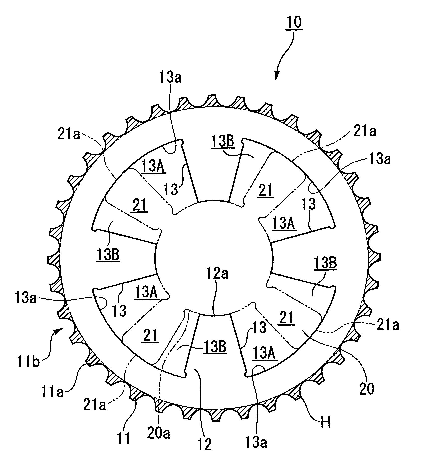
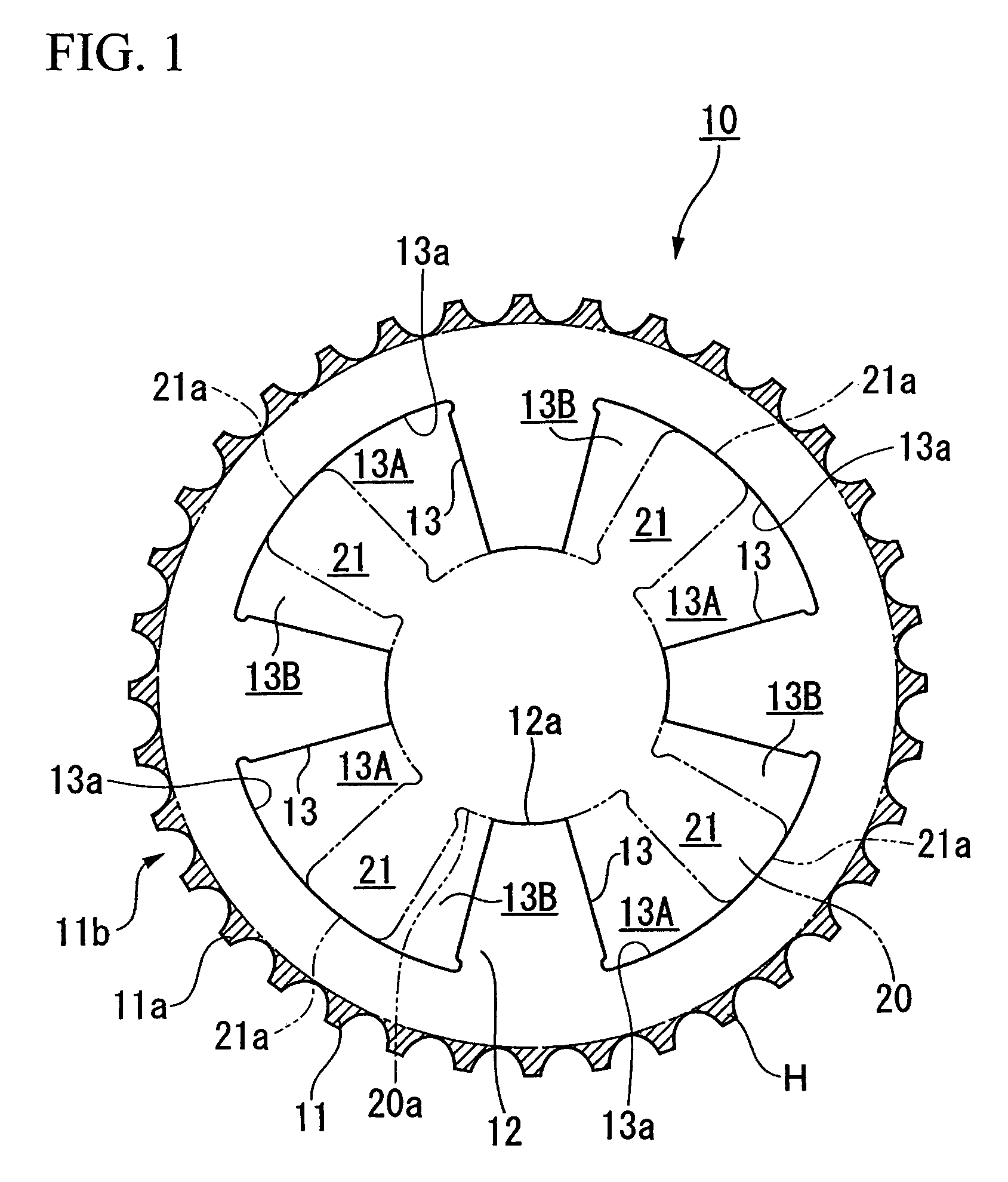
[0028]FIG. 1 shows the shape of an integrated sprocket and housing 10 of the present invention. The integrated sprocket and housing 10, which is used in a variable valve timing mechanism of an internal combustion engine installed in an automobile, is formed as a sintered body composed integrally of a ferrous powder material. The integrated sprocket and housing 10, which is formed in a substantially cylindrical shape, includes a sprocket portion 11 which is disposed in the outer circumferential area thereof, and a housing portion 12 which is disposed inside the sprocket portion 11.

[0029]The sprocket portion 11 is formed as a driving power transmission portion which, in use, engages a roller chain. The sprocket portion 11 includes teeth 11a formed on the outer circumference 11b thereof; therefore, in use, surface pressure and friction are applied to the teeth 11a from the rolle...


PUM

PropertyMeasurementUnit
Lengthaaaaaaaaaa
Thicknessaaaaaaaaaa
Massaaaaaaaaaa

Abstract

An integrated sprocket and housing used in a variable valve timing mechanism. The integrated sprocket and housing includes: a sprocket portion which is formed in a substantially annular shape, and which has teeth on the outer circumference thereof; and a housing portion which is disposed inside the sprocket portion, which has recesses in the inside thereof, and which is formed integrally with the sprocket portion as a sintered body made of a ferrous powder material, wherein the entire surface of the sprocket portion and the housing portion is covered with a steam oxidized layer which is formed by a steam treatment, and a nitrided layer which is formed by a gas soft nitriding treatment subsequent to the steam treatment.

Description

BACKGROUND OF THE INVENTION[0001]1. Field of the Invention[0002]The present invention relates to an integrated sprocket and housing which is, in particular, used in a variable valve timing mechanism, and which includes a sprocket portion which is formed in a substantially annular shape, and which has teeth on the outer circumference thereof, and a housing portion which is disposed inside the sprocket portion, and which has recesses in the inside thereof. The present invention also relates to a method for manufacturing an integrated sprocket and housing.[0003]Priority is claimed on Japanese Patent application No. 2002-275411, filed Sep. 20, 2002, which is incorporated herein by reference.[0004]2. Description of Related Art[0005]In internal combustion engines installed in automobiles, variable valve timing mechanisms, by which open and close timing (valve timing) is changed, have been employed, in order to improve the efficiency of combustion in a low revolution range as well as in a ...

Claims


Application Information

Patent Timeline
IPC IPC(8): C23C8/26F16H55/06F16H55/30F01L1/34B22F5/08C23C8/80F01L1/344
CPCB22F5/08C23C8/26C23C8/80F01L1/3442F01L1/022F01L2103/00F01L2101/00F01L2301/00F01L2303/00F01L1/34
Inventor HARAKAWA, TOSHIRO
Owner DIAMET CORP
Learn More