Discharging sand from a vessel at elevated pressure

Inactive Publication Date: 2007-02-20
AXSIA SERCK BAKER
View PDF7 Cites 3 Cited by
  • Summary
  • Abstract
  • Description
  • Claims
  • Application Information

AI Technical Summary

Benefits of technology

[0018]The objective of this invention is to overcome the problem described above to extend the operational life of pressure dropping cyclones used to drop the pressure of a flow of slurry from a pressurised sand accumulation vessel, or any other vessel containing sand which operates at an elevated pressure.
[0039]wherein the diluting component is controlled by a flow controller for controlling the amount of the dilution fluid combined with the sand or sand slurry such that flashing is reduced.

Problems solved by technology

The sand that is present in well fluids is detrimental to the oil and gas production operations.
Some of the major effects of the sand are that it increases wear on pumps, valves and other pipeline equipment, damages or cause instrumentation to give incorrect readings, it occupies volume in separator vessels reducing the efficiency of separation taking place in the vessels, and if present in the oil it reduce its quality and value.
Strategies and techniques have been developed to cope with sand in the oil production equipment, but these generally have an economic penalty, because they make the production equipment more costly, reduce its capacity, and require greater levels of manning for its operation and maintenance.
There are oil and gas reservoirs which are not in production because the cost of coping with the expected sand production make them uneconomic.
This is done in some instances but it can have the side effect of reducing the fluid production rate.
It is also known for these wells to be constructed incorrectly or for the filters installed in the wells to fail, and so the sand is still produced.
The problem with this method of discharge is that the pressure of the slurry must be reduced by the valve or other pipeline components as it passes between the underflow compartment and the receiving vessel.
These valves have elastomer elements contacting the flow, and even these valves have a relatively short life in this duty.
The pressure limitation of this type of system arises from the elastomer elements within the valves because they form part of the pressure containing envelope of the valve and are not suitable for higher pressures.
Additionally, dropping larger pressures across these valves would also further reduce their life.
This system design has a number of problems:1. The sand accumulator may only be able to be discharged a certain number of times due to fatigue caused by the necessary depressurisation and pressurisation cycles.2. The batch nature of the discharge process means that the valves are operated frequently, and their operation may need to be automated.3. The valves fitted to the accumulator vessel are required to isolate a flow of slurry, for which they are generally not ideally suited, and hence their life is reduced and their maintenance requirements are increased.4. It may be required that the ports through which fluids flow into or out of the sand accumulator must be fitted with two valves in series with a third valve venting the piping between the two valves to provide satisfactory isolation of pressure.
This increases the number of valves which increases the cost, size, weight, and maintenance requirements of the system.5. Stopping and starting the flow of a slurry increase the chances of a blockage occurring in slurry lines.
While the chances of this occurring are not necessarily increased when compared to the lower pressure system described above, it can be more difficult and time consuming to clear blockages in a higher pressure system because the valves and piping are more difficult to dis-assemble and re-assemble, and greater safety precautions must be taken.
The device operates intermittently, but regardless of this has passed the same amount of sand as it would have if it had run continuously, and has achieved a wear life of nearly 2 years.
The problem with such systems is that if gas or a flashing liquid (a liquid that releases dissolved gas on pressure reduction) conveys the sand, the rate of wear increases because of the higher velocities in the cyclone.

Method used


Image

  • Discharging sand from a vessel at elevated pressure
  • Discharging sand from a vessel at elevated pressure

Examples


Embodiment Construction

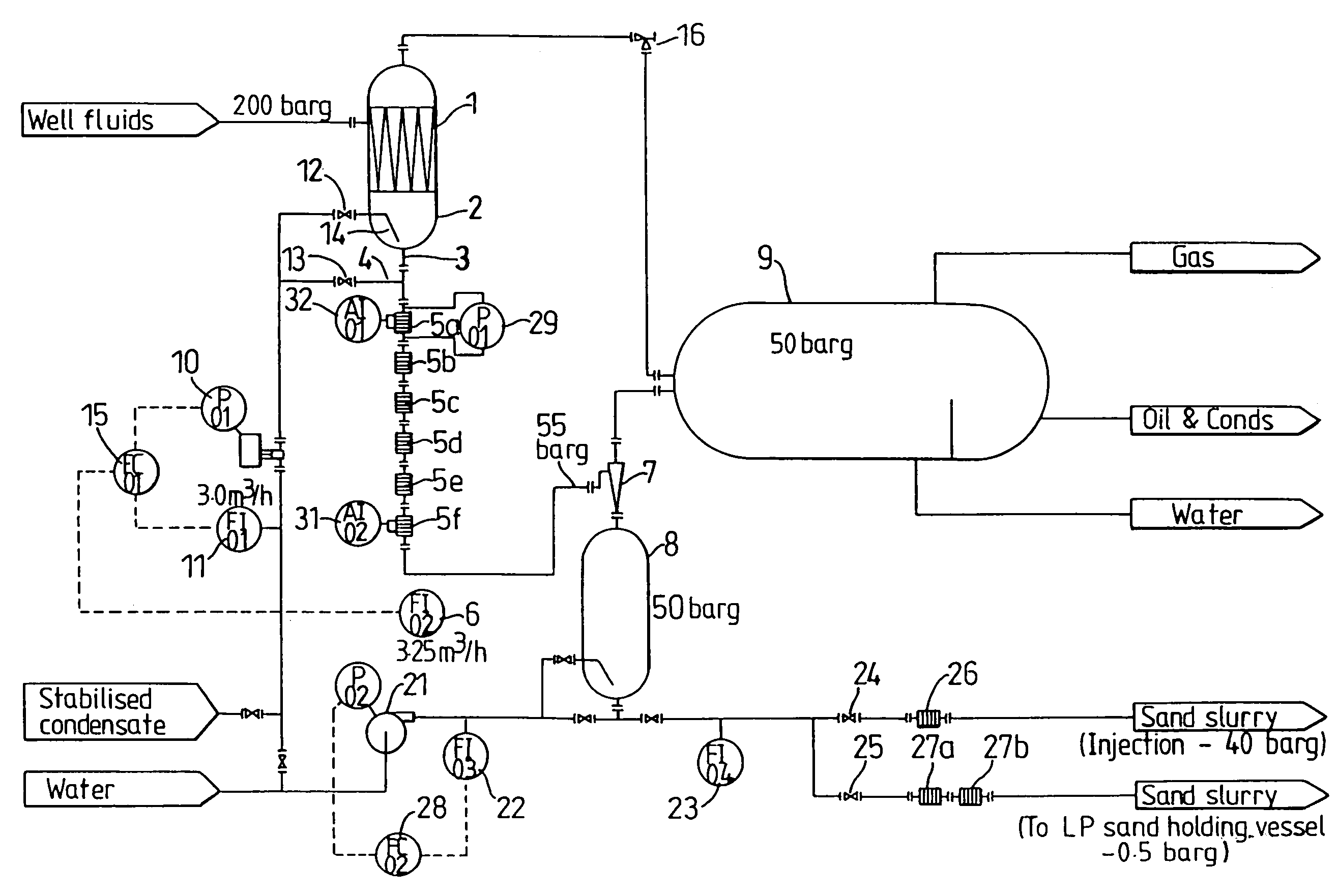
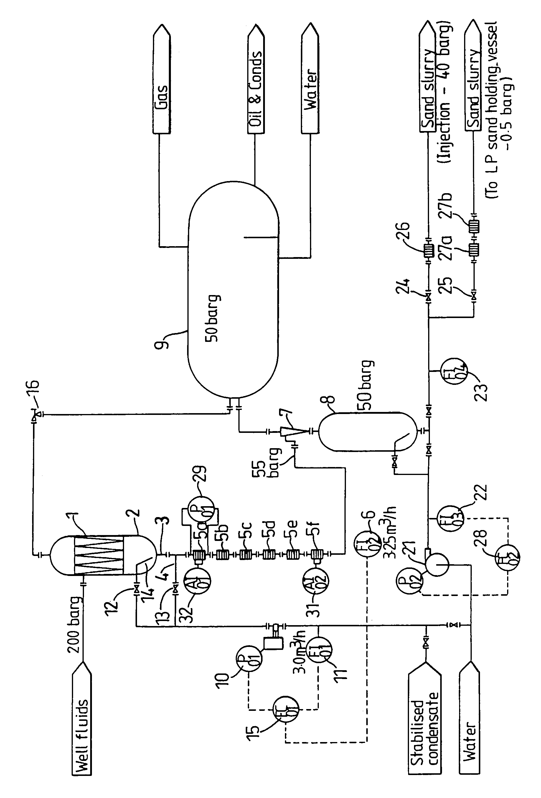
[0042]A wellhead desander vessel 1 receives well fluids from a well at a pressure of 200 barg so as to remove sand from the fluid prior to it entering the wellhead choke valve 16. Sand is separated from the fluids and accumulates within the underflow compartment 2 within the vessel 1. The sand and a small quantity of fluid from the underflow compartment 2 passes out of the desander vessel 1 through an outlet 3 where it combines with dilution fluid fed from a pipe 4 before entering a series of pressure reducing cyclones 5a to 5f where its pressure drops from approximately 200 barg to 55 barg. From the outlet of the last pressure reducing cyclone 5f the slurry flows through flowmeter 6 and then enters hydrocyclone 7 at a pressure of 55 barg where the sand is separated into sand holding vessel 8 operating at 50 barg and the liquid into another vessel 9 (in this example a production separator) operating at 50 barg.

[0043]The dilution fluid is supplied by pump 10 and the flow of the dilut...


PUM

PropertyMeasurementUnit
Fractionaaaaaaaaaa
Fractionaaaaaaaaaa
Pressureaaaaaaaaaa

Abstract

Sand is discharged from a vessel at an elevated pressure and is delivered at a lower pressure. The sand is subjected to the following steps before delivery: I) dilution with a dilution fluid, ii) passage through at least one pressure reducing cyclone, the dilution being such that flashing is reduced, and iii) delivery as a slurry at the delivery pressure. This results in less wear of the components.

Description

BACKGROUND OF THE INVENTION[0001]The present invention relates to discharging sand from a vessel.[0002]The fluids produced by an oil or gas well are gas, oil (or gas condensate) and water. The fluids can also contain solid particles which can be material from the reservoir, scales formed by the water and corrosion products, proppant / frac sand and materials from other sources all of which will be referred to collectively as sand. The flowrate of fluids from a well is controlled by a valve commonly referred to as the wellhead choke valve. The wellhead pressure can be quite high, 200 barg or more, particularly in wells where a large proportion of the fluids is gas and the wellhead choke valve can be required to drop the greater proportion of this pressure. In some cases where solids are present in the well fluids, the wearing parts of wellhead choke valves have a life of a few weeks or less before they must be replaced.[0003]The sand that is present in well fluids is detrimental to the...

Claims


Application Information

Patent Timeline
IPC IPC(8): B01D21/26B03B9/02E21B43/34
CPCB03B9/02B01D21/267E21B43/34E21B43/35
Inventor LANGE, NEVILLE ERNEST
Owner AXSIA SERCK BAKER
Why Eureka
Try Eureka