Low stress to seal expanded PTFE gasket tape

a gasket tape and expansion technology, applied in the field of gaskets, can solve the problems of non-porous ptfe gaskets that are not conformable enough to effectively seal this type of equipment, large amount of unevenness or lack of flatness associated with flanges, and large amount of flanges, etc., to achieve the effect of reducing the tensile strength, and reducing the leakage ra

Active Publication Date: 2007-02-20
WL GORE & ASSOC INC
View PDF18 Cites 33 Cited by
  • Summary
  • Abstract
  • Description
  • Claims
  • Application Information

AI Technical Summary

Benefits of technology

[0013]The present invention is directed to a novel composite tape suitable for use as a gasket, particularly form-in-place gaskets, that provides a substantially air impermeable seal with low load upon the tightening surfaces, and with low stress applied to the gaskets. Gaskets formed from the composite tape of the present invention exhibit excellent dimensional stability and resistance to creep relaxation in both the longitudinal and transverse direction.
[0017]Tensile Strength tests illustrate that the bond strength of the welded joint of the composite tape of the present invention is significantly stronger than the bond strength of other laminated tape. Gasket materials formed from ePTFE film layers laminated perpendicular to the x-y plane of the gasket demonstrate reduced the tensile strength in the width direction compared to the inventive materials. Furthermore, the amount of extension in the inventive materials at maximum stress was significantly less compared to the extension of other materials. The results indicate that gasket materials of the present invention, when compressed between flanges, will be less likely to cold flow.

Problems solved by technology

Unfortunately, non-expanded, non-porous PTFE gaskets are generally not conformable enough to effectively seal this type of equipment.
In the case of glass-lined steel flanges, although there is a relatively smooth finish, there is often a large amount of unevenness or lack of flatness associated with the flanges.
Thus, a non-expanded, non-porous PTFE gasket is not conformable enough to provide an adequate seal in many of these applications.
Unfortunately, in many applications it is not possible to apply sufficient force to the flanges to create enough gasket stress to fully densify the expanded PTFE gasket to create an effective seal.
For example, glass-lined steel piping flanges, glass flanges, or FRP piping flanges may deform, fracture, or break upon the application of a high amount of stress.
Thus, in these applications, an expanded PTFE gasket may not be completely densified to reach a non-porous state, and therefore does not become leak proof, because the maximum stress that can be applied to the flanges without breaking them is not sufficient to densify the gasket.
In some constructions where expanded PTFE gasket is not densified to a substantially non-porous state, leakage can occur through the residual porosity within the gasket.
If a leak of a sufficient rate is present, bubbles will form in the soapy water solution.
In some cases, a leak may exist but a rate small enough not to form a bubble.
Where corrosive chemicals are being processed, the leak may persist for months or years and the corrosive chemicals can eventually leak through the gasket and attack the flange bolts or clamps resulting in a catastrophic failure of the flange.
While this patented construction may overcome many challenges in creating a low stress to seal gasket, there are limitations to the sizes of gaskets that can be produced when cutting gaskets from sheet goods.
Another concern with the manufacturing of such large size gaskets from sheet gasketing materials is the cost associated with producing such gaskets.
For example, tooling costs for large size gaskets can be quite expensive and the manufacturing efficiencies of cutting gaskets from sheet stock can be relatively low especially with large diameter gaskets.
When cutting gaskets from sheet stock, it is not uncommon to experience a sheet utilization yield of only 40% where the remaining 60% of the sheet is scrapped due to center drops, poor nesting of different size gaskets and unused corner sections.
This method, while perhaps suitable for sintered filled PTFE, would not be suitable for soft, porous expanded PTFE which would densify as a result of the applied heat and pressure at the welded joint.
Densification would result in thinner, hard and non-conformable sections within the gasket which would less effectively seal fragile flanges such as glass lined steel and FRP flanges.
However, as previously noted, since adequate gasket stress cannot be applied to densify the ePTFE, these gaskets cannot effectively seal glass lined steel and FRP flanges.
For example, outer air impermeable layers made of incompressible materials such as full density PTFE or densified expanded PTFE may increase the stiffness of the gasket, making it too rigid for a form-in-place gasket.
Therefore, little to no strength is provided to the gasket in the radial direction.
Therefore, gaskets taught in U.S. Patent Publication No. 2003 / 0003290 A1 would be prone to cold flow in the width direction and lack dimensional stability.

Method used


Image

  • Low stress to seal expanded PTFE gasket tape
  • Low stress to seal expanded PTFE gasket tape
  • Low stress to seal expanded PTFE gasket tape

Examples


example 1

[0065]An ePTFE / FEP composite form-in-place gasket of the present invention was produced in the following manner.

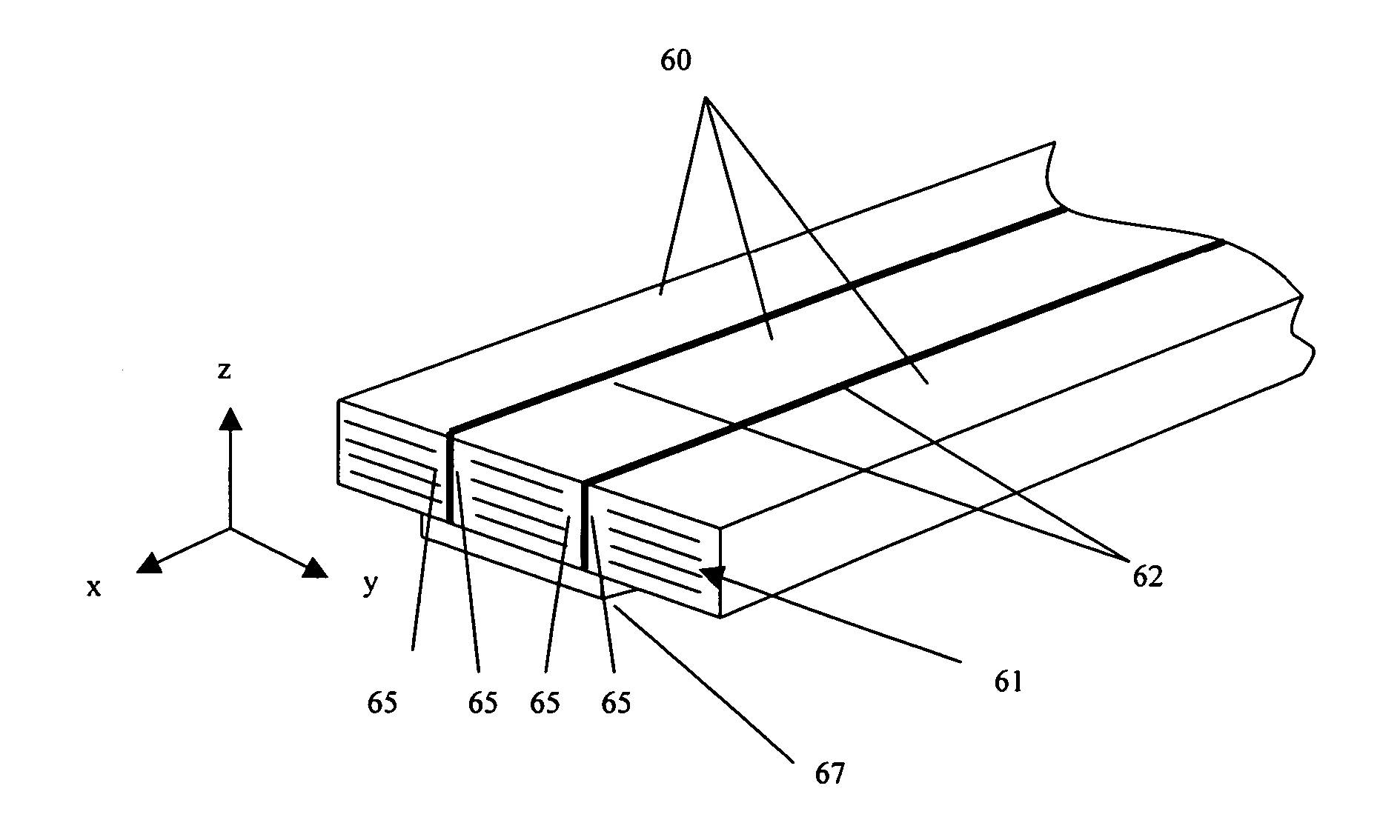
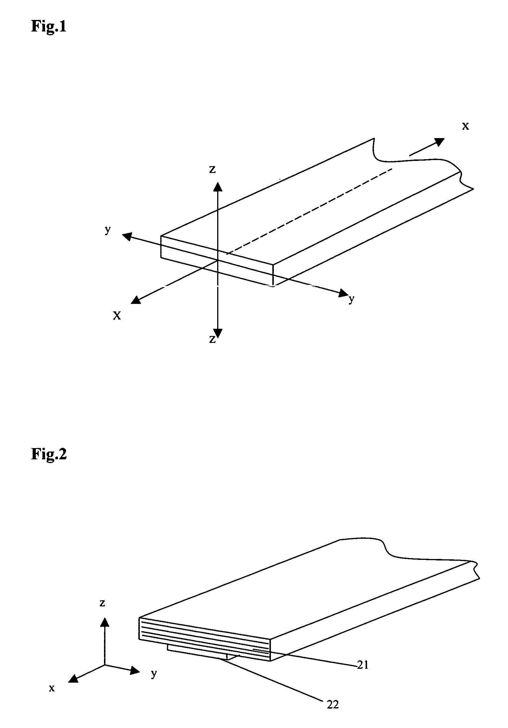
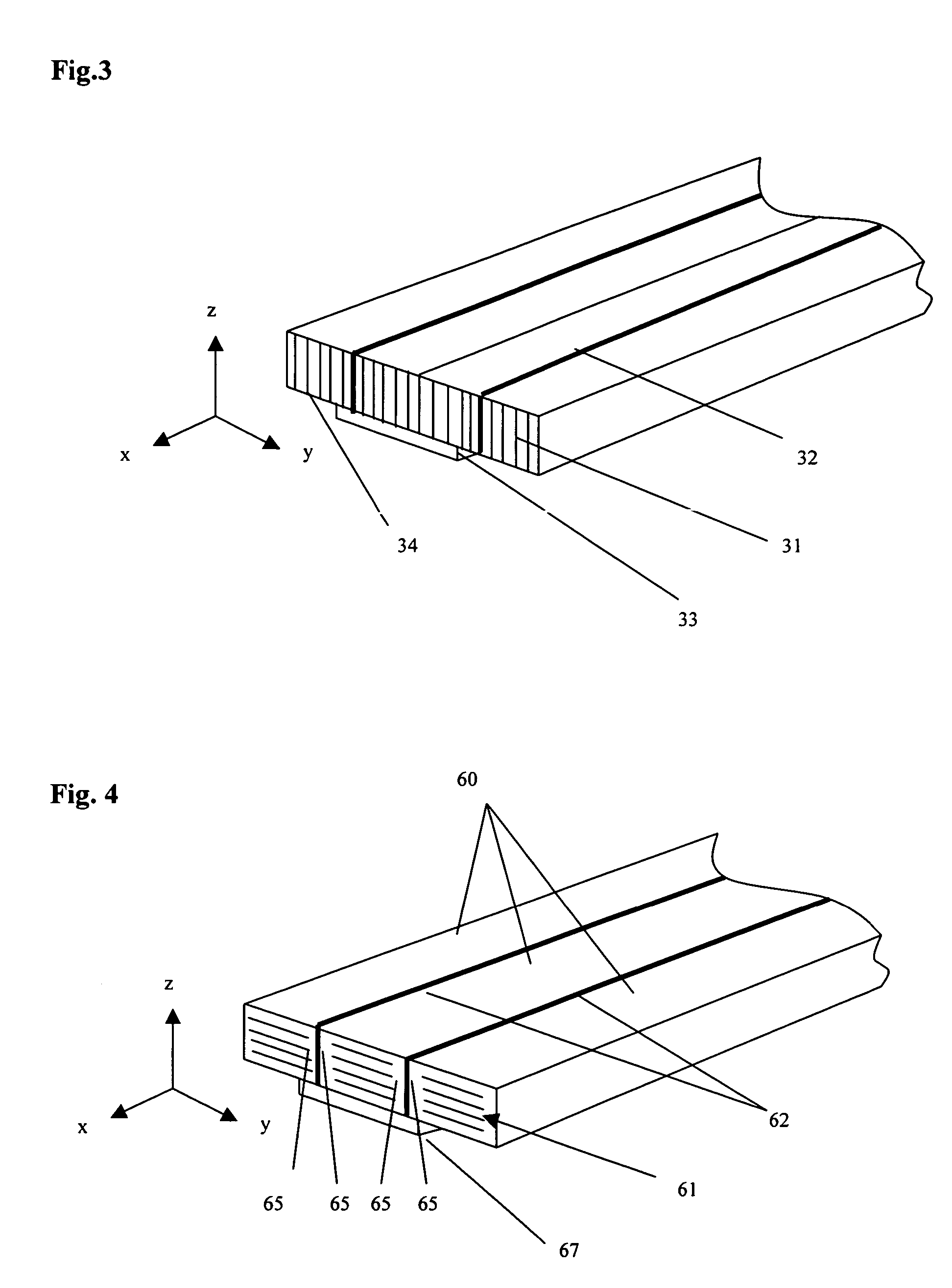
[0066]A length of GORE-TEX® Series 600 Gasket Tape (ePTFE tape) having a nominal width of approximately 20 mm (0.79 inches) and a nominal thickness of approximately 6 mm (0.25 inches) was obtained from W.L. Gore & Associates, Inc. of Newark, Del. The GORE-TEX® Series 600 Gasket Tape is comprised of a plurality of a biaxially expanded PTFE layers laminated in the z-axis having tensile strength in the longitudinal α-axis) and transverse (y-axis) directions as taught in U.S. Pat. No. 5,964,465 to Mills et al.

[0067]A Teflon® FEP Film, Type A having a width of approximately 13 mm (0.5 inches) and a thickness of approximately 0.025 mm (0.001 inches), was obtained from E.I. du Pont de Nemours, Inc. of Wilmington, Del.

[0068]The FEP film was melt bonded to one side surface of the ePTFE tape along the length (x-z plane) using a hot press substantially similar to the press shown in F...

example 2

[0072]An ePTFE / FEP composite form-in-place gasket of the present invention was produced substantially according to the method described in Example 1. The welded tape was trimmed to a final width of about 20.4 mm (0.803 inches) with the FEP layer centered between the two side edges of the welded tape, and the final thickness was about 5.6 mm (0.221 inches). A double-sided pressure sensitive adhesive having a width of about 10 mm was applied to one surface of the tape along the length of the tape and centered between the two edges of the welded tape. The pressure sensitive adhesive was a styrene butadiene rubber (SBR) based adhesive with a polyester carrier film and with a release paper on one side.

[0073]The welded tape made according to this example was formed into a gasket and tested for sealability in accordance with the procedures of the Sealability Test. The results can be found in FIG. 14.

example 3

[0074]An ePTFE / FEP composite form-in-place gasket of the present invention was produced substantially according to the method described in Example 1. The welded tape was trimmed to a final width of about 20.8 mm (0.817 inches) with the FEP layer centered between the two side edges of the welded tape, and the final thickness was about 5.6 mm (0.222 inches). A double-sided pressure sensitive adhesive having a width of about 10 mm was applied to one surface of the welded tape along the length of the tape and centered between the two side edges. The pressure sensitive adhesive was a styrene butadiene rubber (SBR) based adhesive with a polyester carrier film and with a release paper on one side. The welded tape made according to this example was formed into a gasket and tested for sealability in accordance with the procedures of the Sealability Test. The results can be found in FIG. 14.


PUM

PropertyMeasurementUnit
densityaaaaaaaaaa
densityaaaaaaaaaa
densityaaaaaaaaaa

Abstract

A low stress to seal, unitary gasket tape is provided that is particularly suited for use in form-in-place gaskets. The gasket tape preferably comprises at least two joined porous expanded polytetrafluoroethylene (ePTFE) tapes aligned along tape side surfaces and a substantially air impermeable layer there between. The plane of expansion of the ePTFE is substantially parallel to the flange surface providing longitudinal and transverse strength. The substantially air impermeable layer prevents fluid from permeating through the gasket in the radial direction.

Description

BACKGROUND OF THE INVENTION[0001]A wide variety of gaskets are known for use in sealing applications. Porous expanded polytetrafluoroethylene (PTFE) is widely used today as a gasket material. As disclosed in U.S. Pat. No. 3,953,566 to Gore, this material has numerous properties making it highly desirable as a gasket. These properties include being readily compressible and conformable, being chemically resistant, having relatively high strength, and being far less prone to creep relaxation and loss of sealing pressure than non-expanded, non-porous PTFE alone.[0002]Furthermore, gaskets made from biaxially or multiaxially expanded PTFE have improved sealing performance as compared to uniaxially expanded PTFE gaskets. For example, gaskets made from multiaxially expanded PTFE are resistant to creep relaxation and cold flow in multiple directions. The multi-directional tensile strength in multiaxially expanded PTFE gaskets provides circumferential and radial strength to the gasket and inc...

Claims


Application Information

Patent Timeline
Patent Type & Authority Patents(United States)
IPC IPC(8): B32B3/26C09J7/29
CPCB29C65/103B29C66/91933B29C65/5042B29C65/5057B29C65/5078B29C65/5085B29C65/7841B29C65/8215B29C65/8246B29C66/0044B29C66/112B29C66/114B29C66/1142B29C66/1162B29C66/1222B29C66/1226B29C66/1282B29C66/12841B29C66/43B29C66/43441B29C66/435B29C66/71B29C66/723B29C66/727B29C66/919B32B5/32B32B27/20B32B27/322C09J7/0296F16J15/022G01M3/2853B29C65/18B29C65/5071B29C65/8253B29C65/5014B29C65/5021B29C65/5028B29C66/4322B29C66/4324B29C66/472B29C66/836B29C66/91411B29C66/949B29L2031/265B32B2307/72B32B2581/00C09J2201/606C09J2400/243C09J2427/006G01N2203/0017B29C66/91423B29C65/4815B29C65/4825B29C66/9121B29C66/9141B29K2027/18B29C66/7212B29C66/49B29C66/72341C09J7/29Y10T428/249986Y10T428/249981Y10T428/249992Y10T428/249991Y10T428/249988C09J2301/302B29K2305/00
Inventor DOVE, KEVIN E.
Owner WL GORE & ASSOC INC
Why Eureka
Try Eureka