Channel equalizer in digital TV receiver

a digital tv receiver and equalizer technology, applied in the direction of amplitude demodulation, line-faulst/interference reduction, baseband system details, etc., can solve the problem of inability to obtain the original signal only from the received signal, inability to restore a whole picture,

Inactive Publication Date: 2007-02-20
LG ELECTRONICS INC
View PDF18 Cites 12 Cited by
  • Summary
  • Abstract
  • Description
  • Claims
  • Application Information

AI Technical Summary

Benefits of technology

[0024]The time domain equalizer makes coefficient renewal faster than a field synchronization period.

Problems solved by technology

Since the reflected components distort an original signal, it is impossible to obtain the original signal only from the received signal.
The signal distorted thus causes a bit detection error at the digital TV receiver, such that restoration of a whole picture is impossible, or a totally different picture is displayed.
That is, since there are many cases the fading is faster than 24.2 ms in an actual environment, the equalizer in FIG. 1 can not provide a proper performance.

Method used


Image

  • Channel equalizer in digital TV receiver
  • Channel equalizer in digital TV receiver
  • Channel equalizer in digital TV receiver

Examples


first embodiment

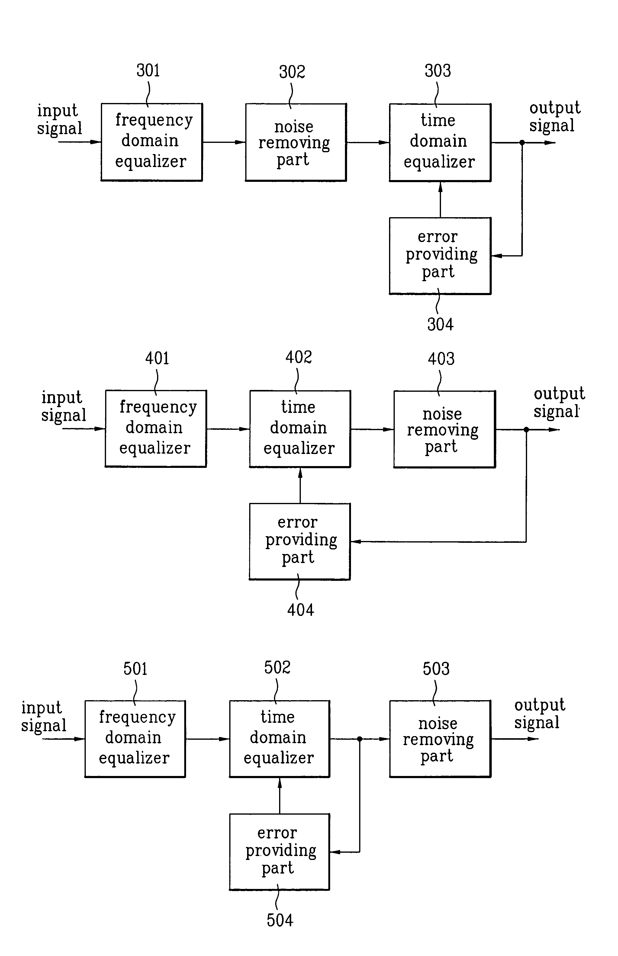
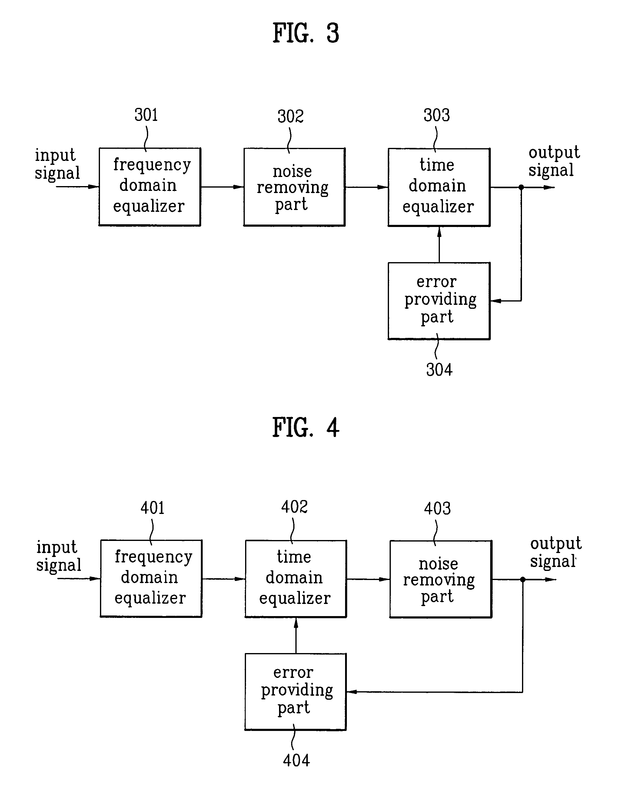
[0046]Referring to FIG. 4, there is a frequency-domain equalizer 401 with an output terminal connected to a time domain equalizer 402, to an output terminal of which a noise removing part 402 is connected, a signal from which is provided to an error providing part 404. The operation of each of the units may or may not be identical to the units of the first embodiment, of which description will be omitted, as it does not make any difference even if the operation of the units is identical.

second embodiment

[0047]That is, in the second embodiment equalizer shown in FIG. 4, the time domain equalizer 402 is provided between the frequency domain equalizer 401 and the noise removing part 403, and the error providing part 404 uses the signal passed through the noise removing part 403 for calculating an error required for renewal of a coefficient of the time domain equalizer 402.

[0048]Thus, since the time domain equalizer 402 is provided before the noise removing part 403, the noise removal can be made more effectively as the fading is removed before removal of the noise. Moreover, since the error for the time domain equalizer 402 is calculated from a signal having the noise removed therefrom, a better quality error can be obtained.

[0049]FIG. 5 illustrates a block diagram of a channel equalizer in a digital TV receiver in accordance with a third preferred embodiment of the present invention, wherein, different from FIG. 4, an error is obtained from a signal passed through time domain equaliz...

third embodiment

[0051]That is, in the third embodiment equalizer shown in FIG. 5, the time domain equalizer 502 is provided between the frequency domain equalizer 501 and the noise removing part 503, and the signal passed through the time domain equalizer 502 is used for calculating an error required for renewal of a coefficient of the time domain equalizer 502.

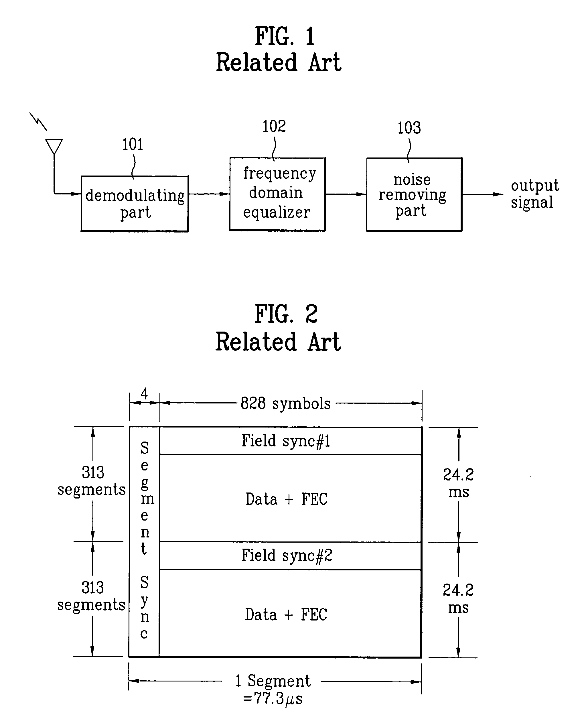
[0052]Thus, by combining the related art channel equalizer with a time domain equalizer, the channel equalizer of the present invention solves the problem of coefficient renewal speed of the related art caused by renewal of the coefficient at every field synchronization only by using the frequency domain equalizer.

[0053]As has been described, by making time domain equalizing after frequency domain equalizing, the channel equalizer in a digital TV receiver of the present invention can improve the problem of slow coefficient renewal caused when only a frequency domain equalizer is used.


PUM


Abstract

Channel equalizer of VSB modulation system in a digital TV receiver, including a frequency domain equalizer for equalizing a received signal to remove a distorted component from the received signal, a noise removing part for removing noise from the equalized signal, a time domain equalizer for equalizing a signal from the frequency domain equalizer or the noise removing part to remove a distorted component from the signal, and an error providing part for estimating an error required for renewal of a coefficient at the time domain equalizer by using a signal from the time domain equalizer or the noise removing part, and feeding the error back to the time domain equalizer.

Description

[0001]This application claims the benefit of the Korean Application No. P2002-67136 filed on Oct. 31, 2002, which is hereby incorporated by reference.BACKGROUND OF THE INVENTION[0002]1. Field of the Invention[0003]The present invention relates to a channel equalizer in a digital TV receiver of a VSB (Vestigial Side Band) modulation system.[0004]2. Description of the Related Art[0005]In most of current digital transmission systems, and an ATSC (Advanced Television Systems Committee) 8VSB transmission system suggested as a digital TV (DTV) transmission system for the USA, when a broadcasting signal is transmitted on a channel through air or a line, the digital TV receiver receives the broadcasting signal together with signals reflected at different reflectors. Since the reflected components distort an original signal, it is impossible to obtain the original signal only from the received signal. The components that distort the original signal are ghost, or fading, or the like.[0006]The...

Claims


Application Information

Patent Timeline
Patent Type & Authority Patents(United States)
IPC IPC(8): H04N5/44H04B1/10H04L25/08H04N7/015H04N5/21
CPCH04N5/211H04L25/03H04N5/4401H04L25/03146H04L25/03159H04N21/426H04N7/015
Inventor KIM, WOO CHAN
Owner LG ELECTRONICS INC
Why Eureka
Try Eureka