
Luminescence measuring device with pre-filter effect suppression
a technology of prefilter effect and measurement device, which is applied in the direction of material analysis, instruments,spectrum investigation, etc., can solve the problems of increasing the dispersion of analyses, increasing the cost of various measurement types, and inconvenient in-line analysis of luminescence techniques
- Summary
- Abstract
- Description
- Claims
- Application Information
AI Technical Summary
Benefits of technology
Problems solved by technology
Method used
Image

Examples
Embodiment Construction
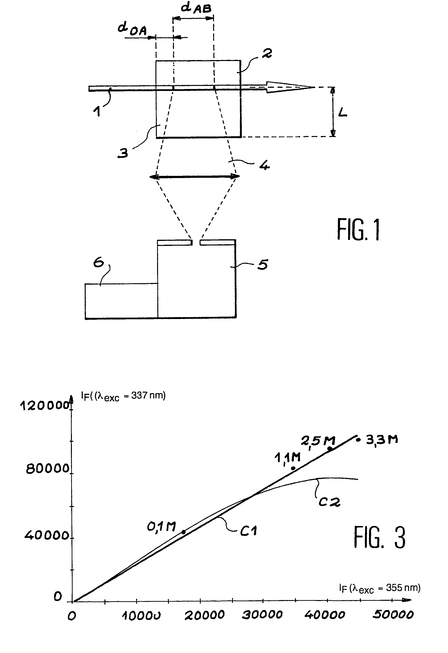
[0041]FIG. 1 has already been described above, therefore there is no point in describing it again.
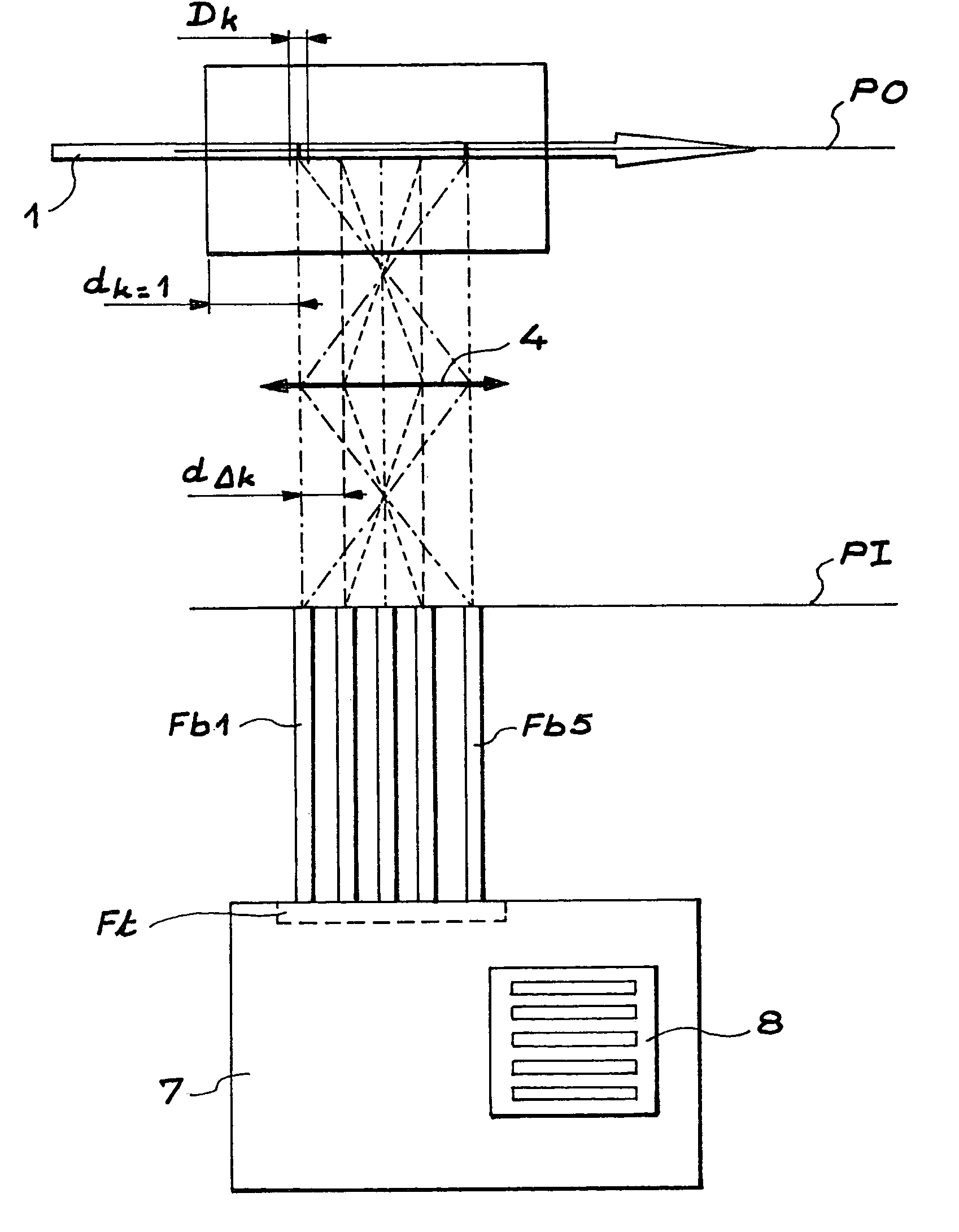
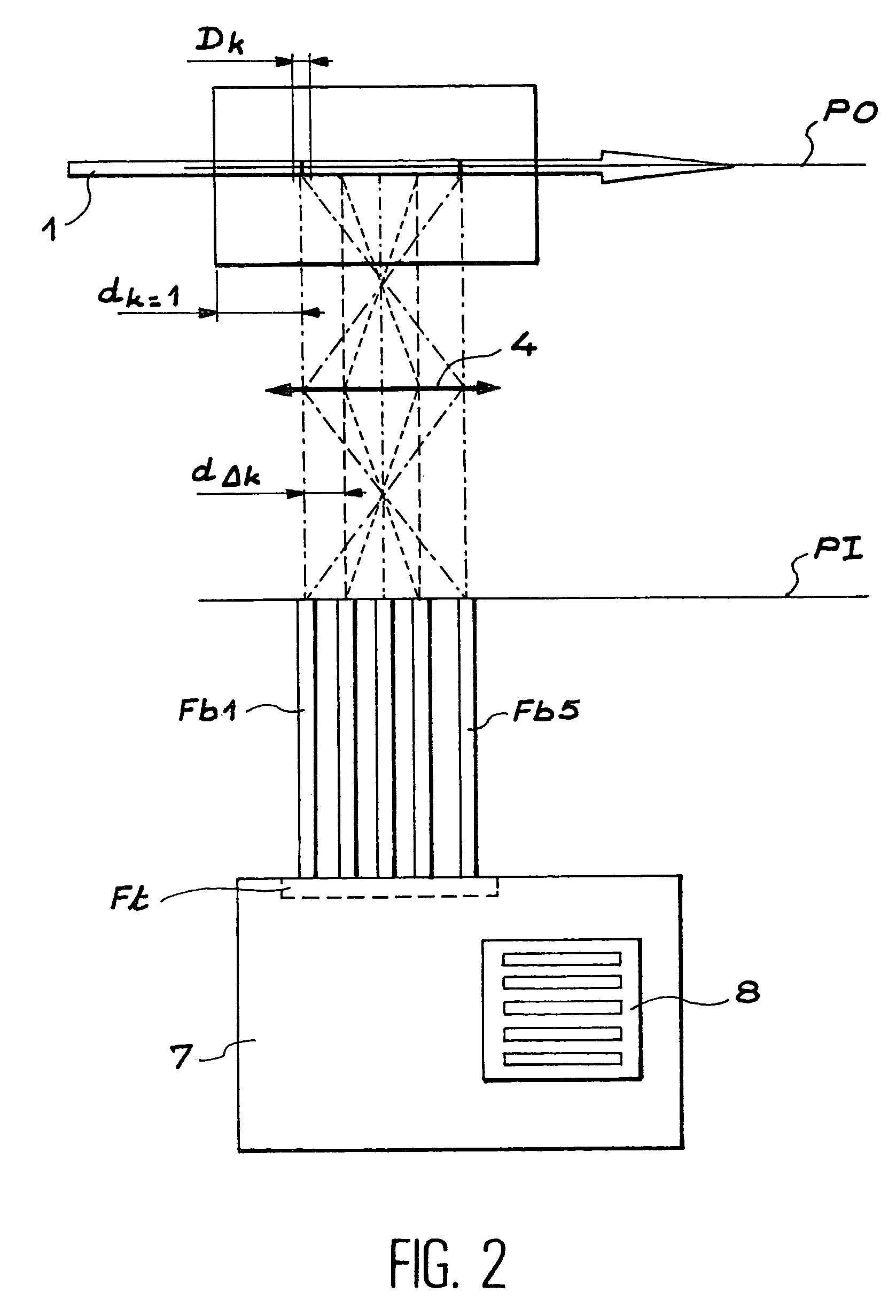
[0042]FIG. 2 shows a luminescence measurement device according to the invention. The measurement device comprises an optical lens 4 preferably installed in double focus (2f), a set of n optical fibres Fbi (5 optical fibres are shown in FIG. 2 as a non-limitative example) and a plane field spectrometer 7.
[0043]An assembly type other than the double focus optical assembly may also be used, but there would then be the disadvantage that the system could not be easily calibrated.
[0044]The excitation radiation 1 passes through the measurement cell 2. The luminescence radiation emitted in the direction approximately perpendicular to the beam axis is collected on the optical lens 4. The chemical species is probed along a trajectory located in the object plane PO of the lens. The number of n of optical fibres is equal to at least 2. Each optical fibre collects a fraction of the luminescence imag...
PUM
| Property | Measurement | Unit |
|---|---|---|
| focal length | aaaaa | aaaaa |
| emission wavelength | aaaaa | aaaaa |
| excitation wavelength | aaaaa | aaaaa |
Abstract
Description
Claims
Application Information