Acoustical receiver housing for hearing aids

a receiver and acoustic technology, applied in the field of receivers, can solve the problems of receivers creating undesirable feedback signals, providing some level of sturdiness, and reducing the service life of receivers, so as to improve service life, improve service life, and give some stiffness and acoustic isolation

Inactive Publication Date: 2007-02-20
SONION NEDERLAND +1
View PDF49 Cites 99 Cited by
  • Summary
  • Abstract
  • Description
  • Claims
  • Application Information

AI Technical Summary

Benefits of technology

[0012]By adding the jacket at strategic places on the housing, a very stiff package can be made. Further, by choosing the right material other factors can also be optimized. For example, a soft magnetic material can assist in electromagnetic shielding. If magnetic shielding is not an issue, it might be better to use stainless steel, which has a higher hardness and can give some stiffness and acoustical isolation in a smaller package. For telecom applications a plasti

Problems solved by technology

First, the housing provides some level of sturdiness.
In either a telecommunication system or a hearing aid, the gain introduced between the microphone and the receiver may result in feedback problems.
The vibration or acoustical radiation of the receiver creates an undesirable feedback signal that is received by the microphone.
Furthermore, in a hearing aid with a telecoil, a magnetic feedback signal may create feedback problems.
Disfiguring the housing can easily occur because the housing material is thin and has a low hardness.
One common type of d

Method used


Image

  • Acoustical receiver housing for hearing aids
  • Acoustical receiver housing for hearing aids
  • Acoustical receiver housing for hearing aids

Examples


Embodiment Construction

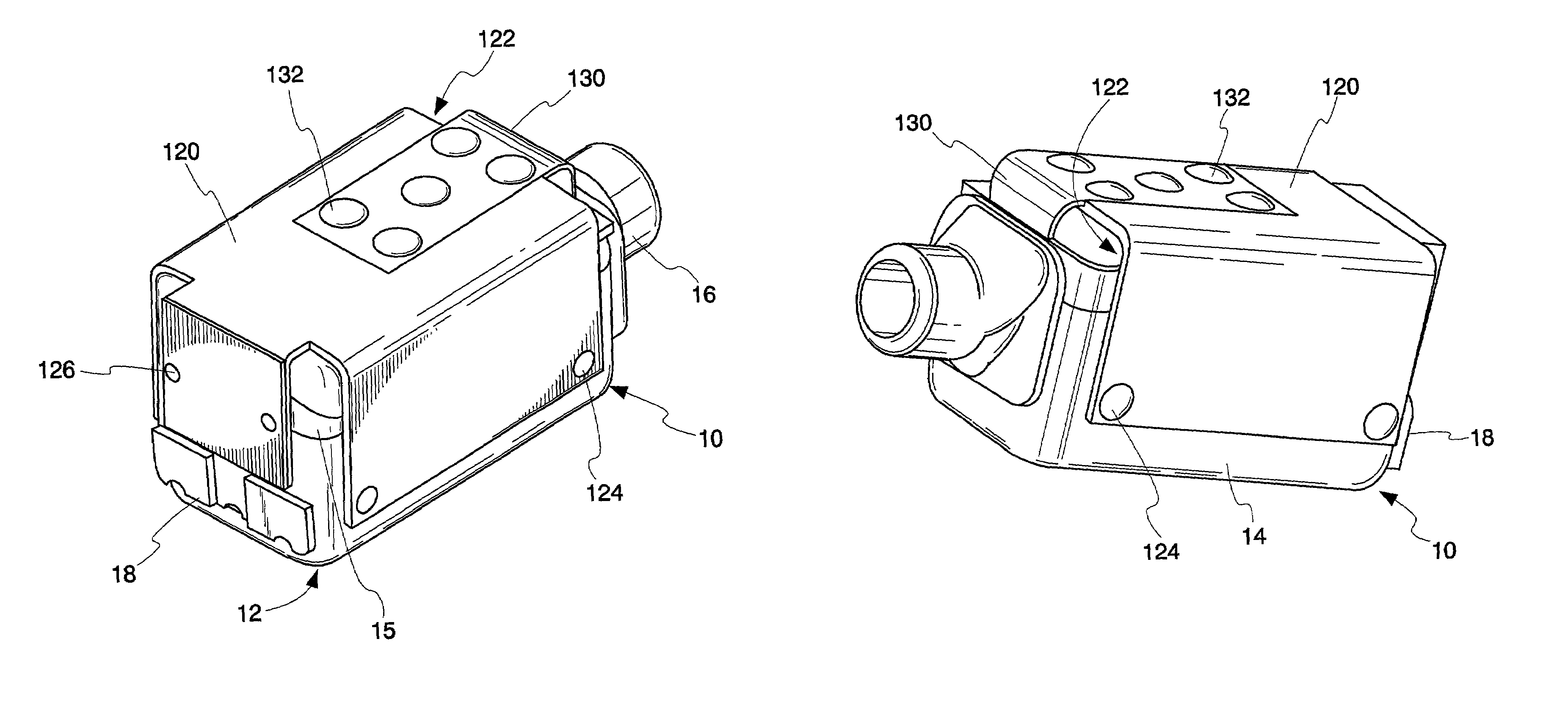
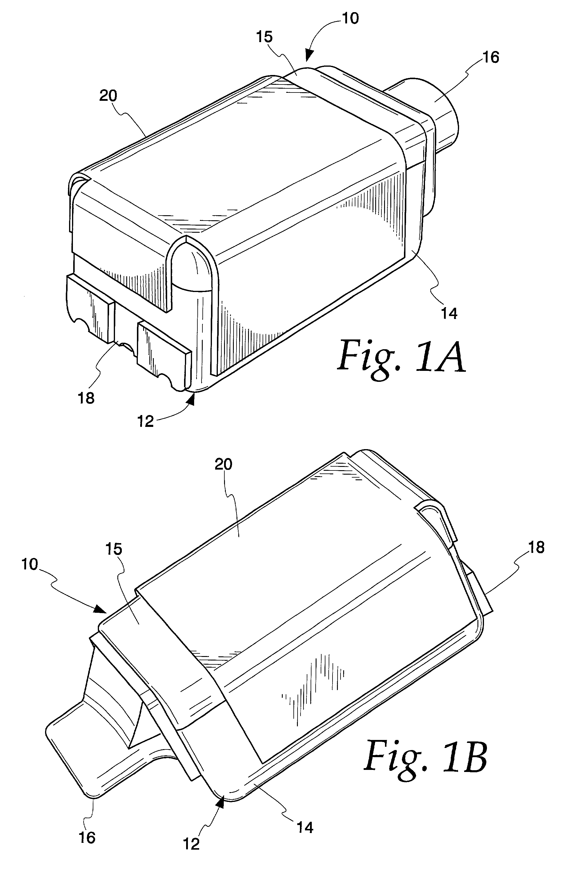
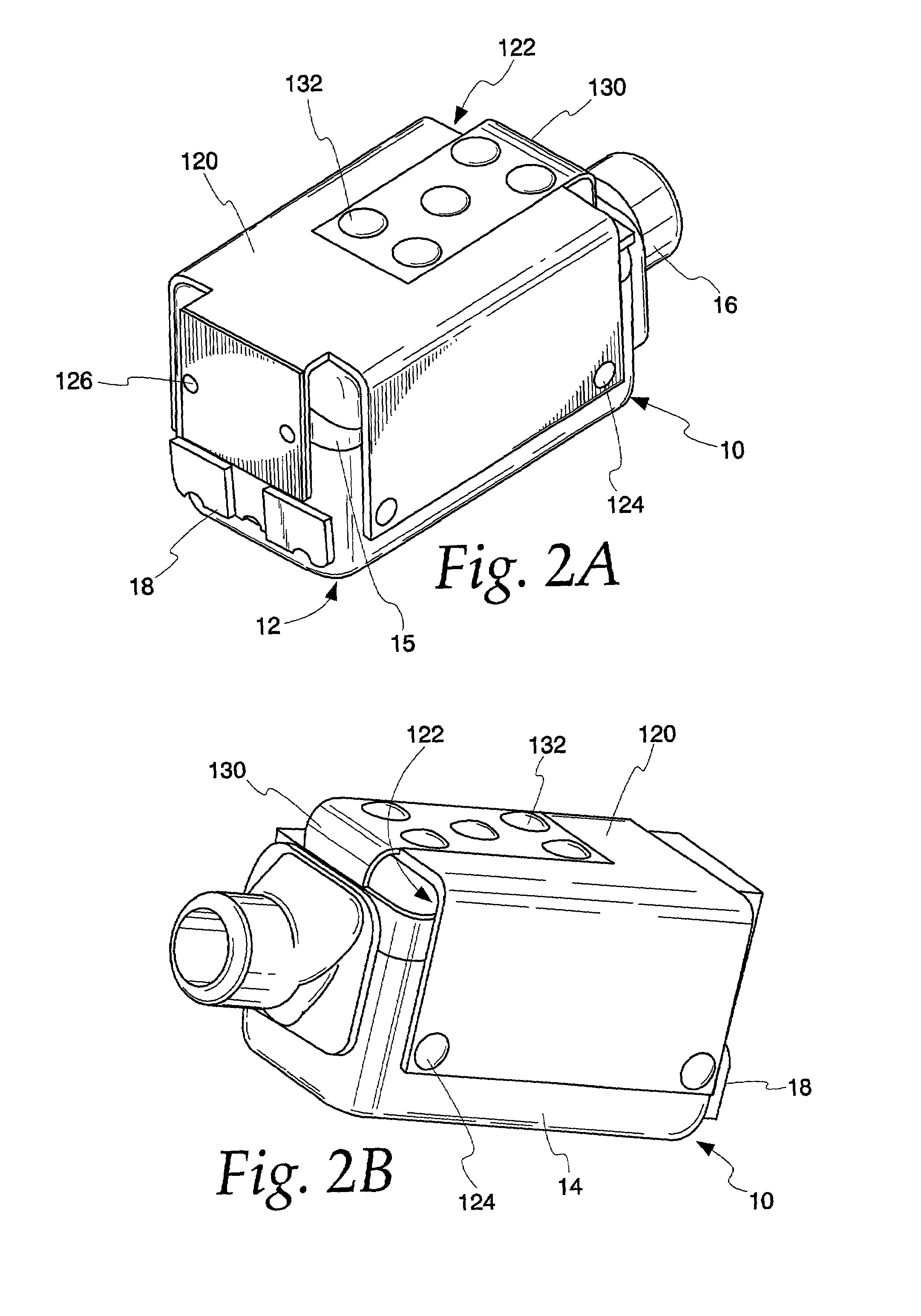
[0024]FIGS. 1A and 1B illustrate a first embodiment of the present invention. An acoustic receiver 10 includes various working components that convert an input audio signal into an acoustic signal. These working components typically include several electromagnetic components that move a drive element coupled to a diaphragm for creating the acoustic signal. In the disclosed embodiment, the receiver 10 is a balanced armature receiver. An example of a receiver is disclosed in commonly assigned U.S. Pat. No. 6,075,870, titled “Electroacoustic Transducer With Improved Shock Resistance,” which is incorporated herein by reference in its entirety.

[0025]A housing 12 surrounds the working components and includes a case 14 and a cover 15 above the case 14. The housing 12 has six sides, each of which is generally rectangular. Of course, the housing 12 may take the form of various shapes (e.g., cylindrical, D-shaped, or trapezoid-shaped) with a different number of sides. One end surface of the h...


PUM


Abstract

An acoustic receiver comprises means for converting an input audio signal into an acoustic signal. The receiver has a housing having a plurality of sides that surround the converting means. One of the sides include an output port for broadcasting the acoustic signal. A jacket fits around the housing and has sections for engaging the sides. The sections are generally flat. The jacket may also form a gap with a corresponding side surface of the housing. A printed circuit board can be located within the gap. The printed circuit board including electronics for processing said input audio signal.

Description

RELATED APPLICATION[0001]This application claims the benefit of priority of U.S. Provisional Patent Application No. 60 / 252,756, filed Nov. 22, 2000.FIELD OF THE INVENTION[0002]The invention relates to receivers used in telecommunications equipment and hearing aids. In particular, the present invention relates to a housing having improved sturdiness and electromagnetic shielding while still maintaining small dimensions.BACKGROUND OF THE INVENTION[0003]A conventional hearing aid or listening device can include both a microphone and a telecoil for receiving inputs. The microphone picks up acoustic sound waves and converts the acoustic sound waves to an audio signal. That signal is then processed (e.g., amplified) and sent to the receiver (or “speaker”) of the hearing aid or listening device. The speaker then converts the processed signal to an acoustic signal that is broadcast toward the eardrum.[0004]On the other hand, the telecoil picks up electromagnetic signals. The telecoil produc...

Claims


Application Information

Patent Timeline
IPC IPC(8): H04R25/00H04R1/28H04R1/38
CPCH04R25/65H04R25/604H04R2225/49H04R2209/027
Inventor VAN HALTEREN, AART ZEGERVAN HAL, PAUL CHRISTIAAN
Owner SONION NEDERLAND
Why Eureka
Try Eureka