Method for adjusting alignment of laser beams in combined-laser-light source where the laser beams are incident on restricted area of light-emission end face of optical fiber

a laser beam and laser beam technology, applied in the field of laser beam alignment, can solve the problems of long time, difficult powering of semiconductor lasers, long time required for gan semiconductor lasers, etc., and achieve the effects of reducing the startup time of combined laser beams, accurate injection of the entire bundle of laser beams, and reducing the number of laser beams

Inactive Publication Date: 2007-02-20
ADTEC ENG +1
View PDF21 Cites 97 Cited by
  • Summary
  • Abstract
  • Description
  • Claims
  • Application Information

AI Technical Summary

Benefits of technology

[0032]According to the second aspect of the present invention, it is also possible to accurately inject the entire bundle of laser beams into a restricted concentric region of the core portion which is located at the center of the core portion. Therefore, the startup time of the combined-laser-light source can be reduced.
[0033]That is, in the laser-light alignment method according to the second aspect of the present invention, the light intensity of the combined laser beams outputted from the light-emission end of the optical fiber is measured while moving the convergence lens in a direction perpendicular to the optical axis of the convergence lens so that the center of an area of the end face through which the laser beams emitted from the plurality of semiconductor lasers enter the optical fiber moves along a diameter passing through the center of the core portion. With the movement of the convergence lens, the light intensity measured as above monotonously increases to the maximum value, and monotonously decreases from the maximum value. The relationship between the light intensity and the position of the convergence lens shows a characteristic which is symmetric with respect to the position at which the light intensity is maximized. When the convergence lens is located in a position in which the light intensity is close to the maximum value, variations in the light intensity are small. However, when the convergence lens is located in a position in which the light intensity is substantially smaller than the maximum value, variations in the light intensity are great, and thus it is possible to accurately determine the two positions of the optical axis of the convergence lens at which the light intensity measured in step (b) is equal to a certain value which is smaller than the maximum value of the light intensity measured in step (b). Consequently, when the optical axis of the convergence lens is placed at the middle position between the two positions determined in step (c), it is possible to accurately inject the ...

Problems solved by technology

However, since the lifetimes of the semiconductor lasers (e.g., about 10,000 hours) are shorter than those of the exposure systems, there are demands for powering the semiconductor lasers in each exposure system only when a photosensitive material is exposed, and powering off the semiconductor lasers when no photosensitive material is exposed even during operating time of the exposure system in order to ap...

Method used


Image

  • Method for adjusting alignment of laser beams in combined-laser-light source where the laser beams are incident on restricted area of light-emission end face of optical fiber
  • Method for adjusting alignment of laser beams in combined-laser-light source where the laser beams are incident on restricted area of light-emission end face of optical fiber
  • Method for adjusting alignment of laser beams in combined-laser-light source where the laser beams are incident on restricted area of light-emission end face of optical fiber

Examples


concrete example 1

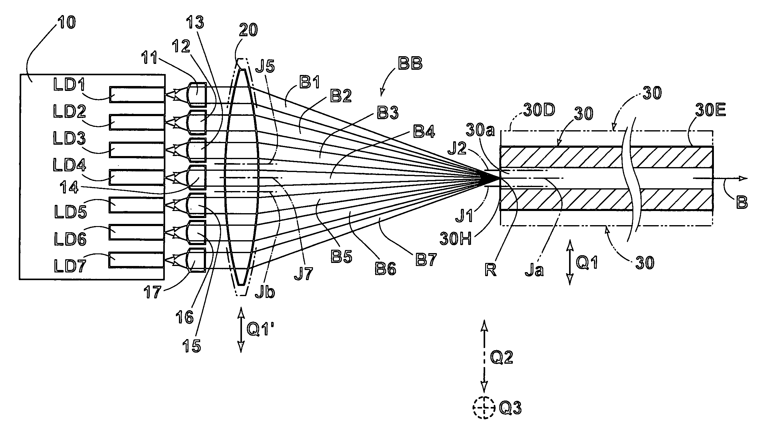
[0098]As illustrated in FIG. 5A, the combined-laser-light source in the concrete example 1 is constructed in such a manner that the laser beams B1 through B7 are incident on the very small central area E5 in the aforementioned concentric area 30b (having the diameter equal to or smaller than the diameter of the core 30a) when the temperature of the combined-laser-light source is steadily controlled. Since the laser beams B1 through B7 are incident on the identical area, only the single area E5 is illustrated in FIG. 5A.

[0099]FIG. 5B shows the startup characteristic F5 of the above combined-laser-light source. As indicated in FIG. 5B, the output power of the combined-laser-light source enters the rated tolerance range H immediately after the powering on of the semiconductor lasers. That is, even when the semiconductor lasers are powered off and are then powered on, the output of the combined-laser-light source can be used immediately after (e.g., within one second of) the powering on...

concrete example 2

[0100]As illustrated in FIG. 6A, the combined-laser-light source in the concrete example 2 is constructed in such a manner that the laser beams B1 through B7 are incident on the areas E6 in the aforementioned concentric area 30b (having the diameter equal to or smaller than the diameter of the core 30a) when the temperature of the combined-laser-light source is steadily controlled, where the areas E6 are located approximately in the upper half of the concentric area 30b. Since the incident laser beams B1 through B7 are spread, the areas E6 on which the laser beams B1 through B7 are incident are spread as illustrated in FIG. 6A.

[0101]FIG. 6B shows the startup characteristic F6 of the above combined-laser-light source. Similar to the concrete example 1, the output power of the combined-laser-light source enters the rated tolerance range H immediately after the powering on of the semiconductor lasers, as indicated in FIG. 6B. That is, even when the semiconductor lasers are powered off ...

concrete example 3

[0106]As illustrated in FIG. 9A, the combined-laser-light source in the concrete example 3 is constructed in such a manner that the laser beams B1 through B7 are incident on the areas E9 in the aforementioned concentric area 30b (having the diameter equal to or smaller than the diameter of the core 30a) when the temperature of the combined-laser-light source is steadily controlled, where the areas E9 are located approximately in the lower half of the concentric area 30b. Since the incident laser beams B1 through B7 are spread, the areas E9 on which the laser beams B through B7 are incident are spread as illustrated in FIG. 9A.

[0107]FIG. 9B shows the startup characteristic F9 of the above combined-laser-light source. As illustrated in FIG. 9B, the output power of the combined-laser-light source enters the rated tolerance range H immediately after (e.g., within one second of) powering on of the semiconductor lasers. That is, even when the semiconductor lasers are powered off and are t...


PUM


Abstract

A combined-laser-light source includes: a plurality of semiconductor lasers; an optical fiber; and an optical system which converges a bundle of laser beams emitted from the plurality of semiconductor lasers, and makes the converged bundle of the laser beams enter the core of the optical fiber so that the laser beams are combined in the optical fiber when the laser beams pass through the optical fiber. The optical system is aligned with the optical fiber so that the converged bundle of the laser beams is incident on an area of an end face of the core when steady temperature control is performed on the combined-laser-light source, where the area is concentric with the end face of the core, and has a diameter equal to or smaller than half of the diameter of the core.

Description

BACKGROUND OF THE INVENTION[0001]1. Field of the Invention[0002]The present invention relates to a laser-light alignment method for adjusting alignment of laser beams emitted from a plurality of semiconductor lasers with an optical fiber in which the laser beams are to be combined (optically multiplexed). The present invention also relates to a combined-laser-light source to which the above laser-light alignment method is applied. The present invention further relates to an exposure system having the above combined-laser-light source.[0003]2. Description of the Related Art[0004]The following documents (1) and (2) disclose information related to the present invention.[0005](1) U.S patent Laid-Open No. 20020090172)[0006](2) Japanese Unexamined Patent Publication No. 2000-338432[0007]Conventionally, various combined-laser-light sources are known. In the combined-laser-light sources, an entire bundle of laser beams emitted from a plurality of semiconductor lasers is converged and enters...

Claims


Application Information

Patent Timeline
IPC IPC(8): G02B6/26H01S3/10G02B6/42
CPCG02B6/4226G02B6/4206G02B6/42
Inventor TERAMURA, YUICHIOKAZAKI, YOJI
Owner ADTEC ENG
Why Eureka
Try Eureka