
Systems, methods and computer program products for continuous emissions monitoring on-line

a technology of continuous emissions monitoring and computer program products, applied in the direction of computer control, testing/monitoring control systems, instruments, etc., can solve the problems of increasing the inherent limitations of the client server architecture, the relative complexity of the client application, and the inability to meet the needs of users and power plants, etc., to achieve high-scale user and power plant scalable

Inactive Publication Date: 2007-02-20
THE BABCOCK & WILCOX CO
View PDF5 Cites 126 Cited by
  • Summary
  • Abstract
  • Description
  • Claims
  • Application Information

AI Technical Summary

Benefits of technology

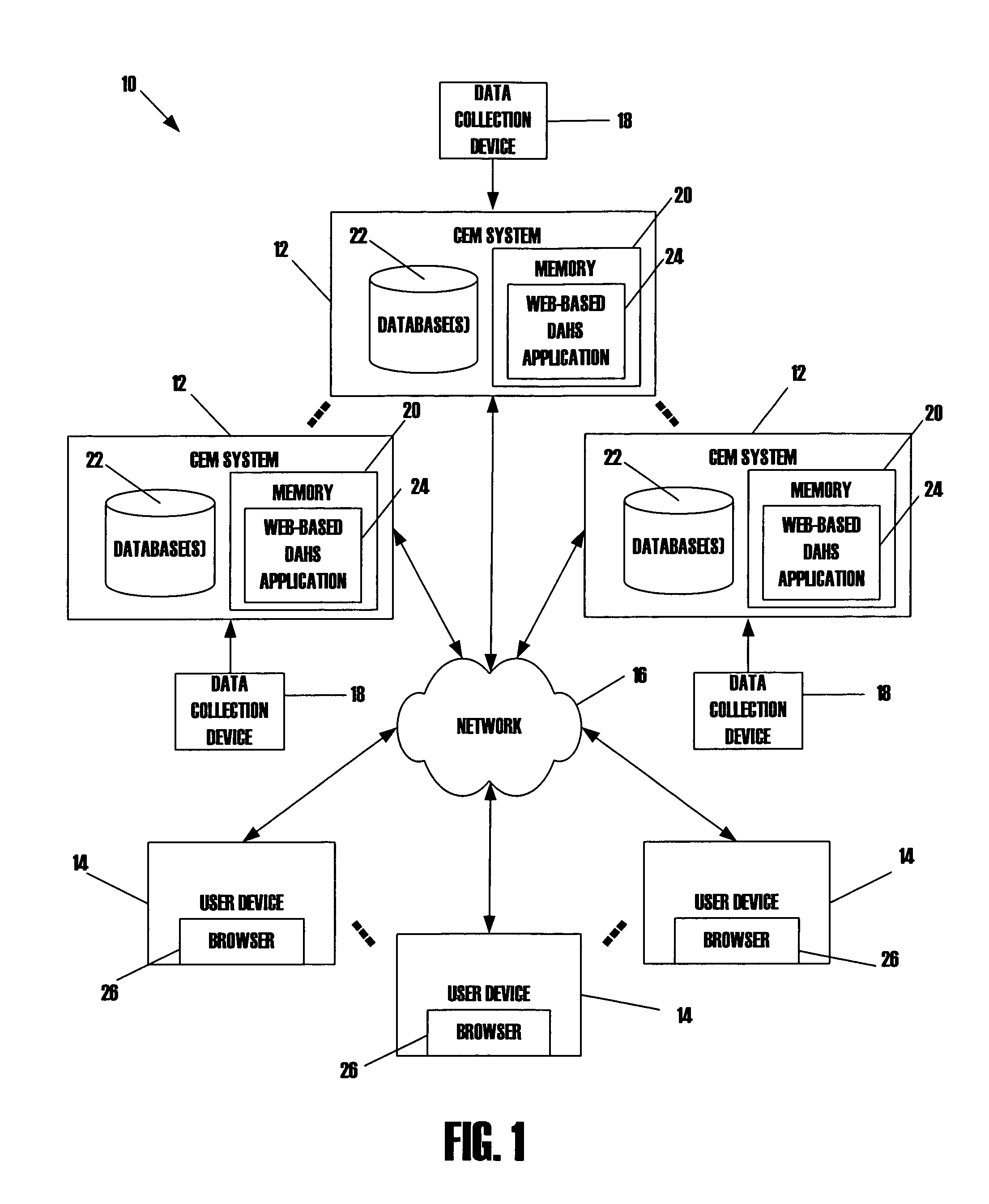
[0010]The present invention is directed generally to systems, methods and computer program products that provide secure access to emissions data from one or more power plants in real-time via a web-based interface. The user accessing the emissions data does not need specialized software on their computing device other than a commercially available Internet browser application. Accordingly, the user is not required to install new software with every upgrade or regulatory change. In addition, a system in accordance with the present invention is highly scalable with regard to users and power plants.

Problems solved by technology

This may require the client application to have multiple modules to be compatible with the different applications running on the server, making the client application relatively complicated.
In addition, a client server configuration has inherent limitations associated with upgrades to both the client and the server software and the compatibility of the various versions.
This is a daunting task, especially given the timing requirements of the upgrades being done virtually simultaneously and the updated version are not backward compatible.
Another inherent limitation of the client server architecture is becoming more and more evident as utility companies expand into different geographic markets.
Accordingly, with each power plant having a CEM system, some utility companies have a relatively large number of CEMs to monitor, each through a separate system, and often time there is no one location with access to all CEMs.
Accordingly, an unsatisfied need exists in the industry for a CEM system that enables efficient monitoring of real-time emission data of a power plant from a remote location.

Method used


Image

  • Systems, methods and computer program products for continuous emissions monitoring on-line
  • Systems, methods and computer program products for continuous emissions monitoring on-line
  • Systems, methods and computer program products for continuous emissions monitoring on-line

Examples


Embodiment Construction

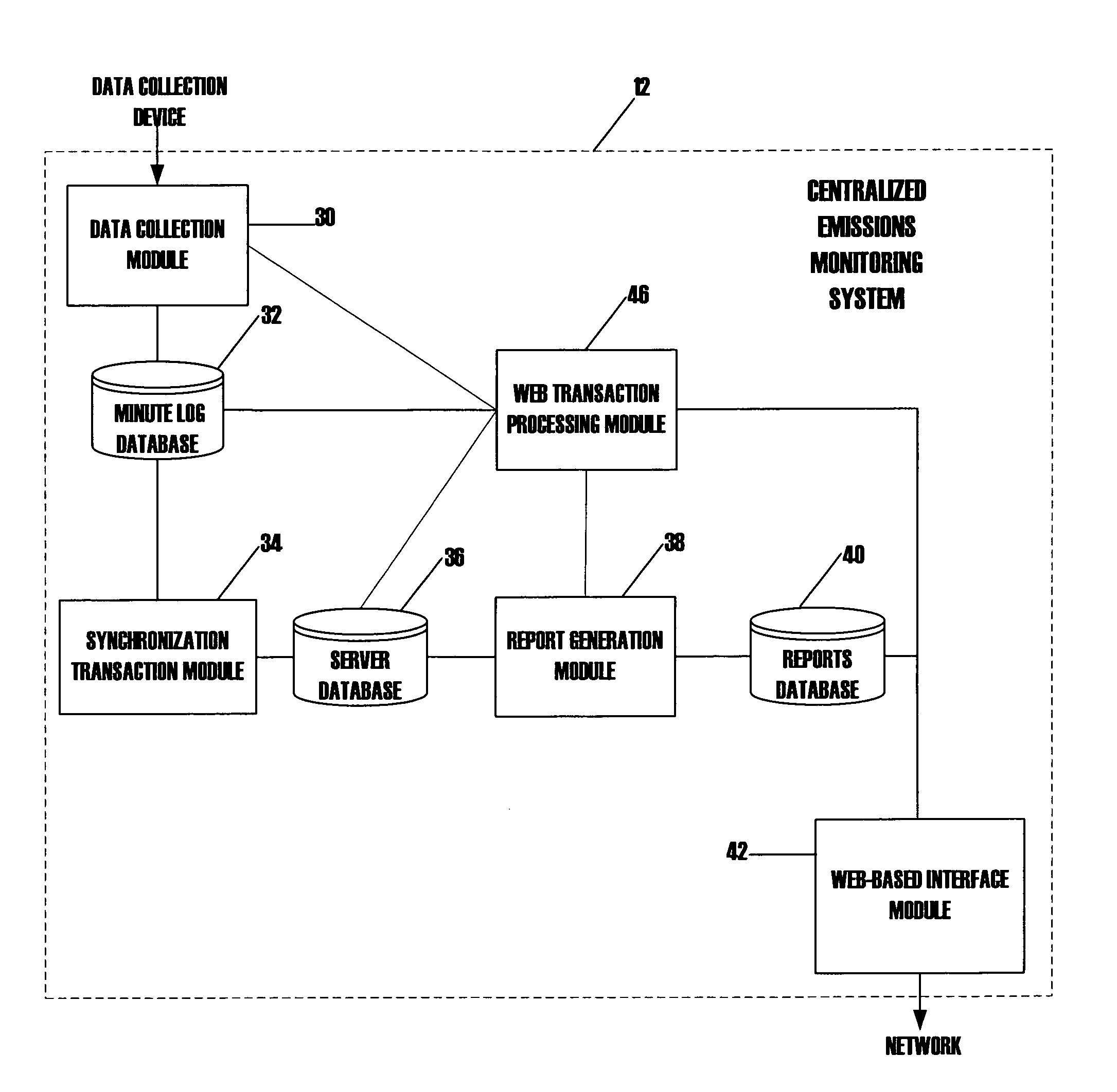
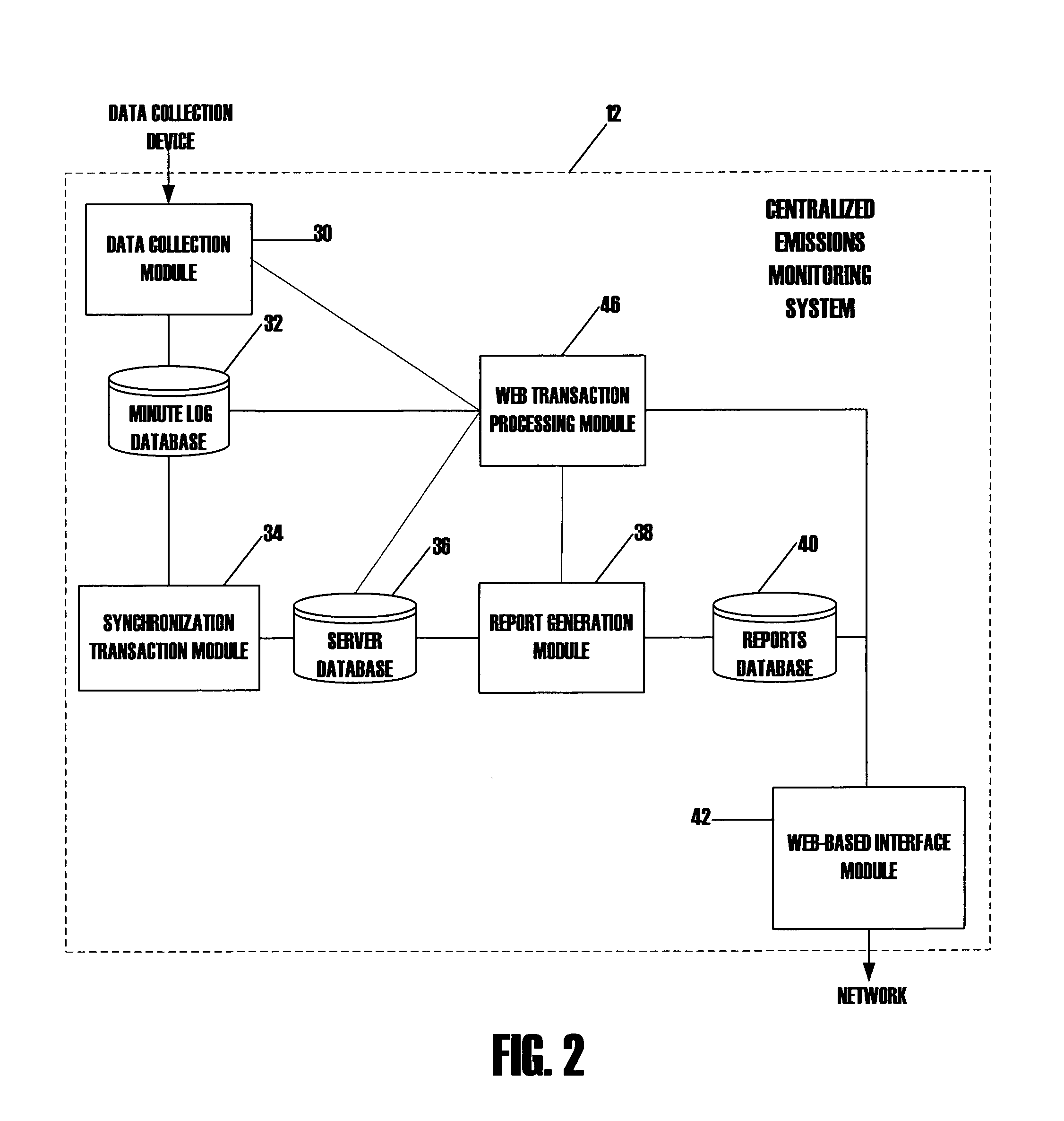
[0035]The present invention will now be described more fully hereinafter with reference to the accompanying drawings, in which preferred embodiments of the invention are shown. This invention may, however, be embodied in many different forms and should not be construed as limiting to the embodiments set forth herein; rather, these embodiments are provided so that this disclosure will be thorough and complete, and will fully convey the scope of the invention to those skilled in the art. Like numbers refer to like elements throughout.

[0036]The present invention is described below with reference to block diagrams and flow chart illustrations of methods, apparatuses (i.e., systems) and computer program products according to an illustrative embodiment of the invention. It will be understood that each block of the block diagrams and flow chart illustrations, and accommodations of blocks in the block diagrams and flow chart illustrations, respectively, can be implemented by computer progra...


PUM


Abstract

Systems, methods and computer program products provide secure access to real-time emissions data from one or more power generating plants via a web-based interface. The user provides log-in information to gain a predefined level of access based on the inputted log-in information, and may access emissions data of one or more power generating plants located remotely with respect to the user. The user can utilize any suitable computing device with a suitable browser application to access the emissions data. Accordingly, the system is highly scalable, in both users and power generating plants being monitored.

Description

BACKGROUND OF INVENTION[0001]The present invention relates to continuous emissions monitoring, and more particularly, to systems, methods and computer program products for providing remote access to real-time emissions data.[0002]The burning of fossil fuels by power generation plants leads to the production of pollutants such as nitrogen oxides (NOx), sulfurous compounds (e.g., SO2), carbon monoxide (CO), and carbon dioxide (CO2) as by-products of the combustion process. In an effort to control the dissemination of these pollutants into the atmosphere, state and Federal governments have enacted laws and regulations restricting the amounts of the aforementioned substances that a power generation plant may emit into the atmosphere.[0003]Since around 1993, continuous emissions monitoring (CEM) systems have been utilized in most fossil-fuel power generation systems to meet the reporting requirements set forth by the Environmental Protection Agency (EPA) and particularly, by 40 C.F.R. §§...

Claims


Application Information

Patent Timeline
Patent Type & Authority Patents(United States)
IPC IPC(8): G06F19/00
CPCG05B15/02G05B23/0267G05B2219/13G05B2223/06Y04S10/52
Inventor WHIFFEN, RICHARD C.MCDADE, TIMOTHY P.GONG, XIAODALAWSON, WILLIAM H.HA, KHOI T.
Owner THE BABCOCK & WILCOX CO
Learn More