Control device for spark-ignition engine

a control device and spark ignition technology, applied in the direction of electric control, ignition automatic control, manual lubrication, etc., can solve the problems that the provision of nox catalyst becomes unnecessary, and achieve the effects of improving fuel economy, reducing engine load, and increasing air-fuel ratio

Inactive Publication Date: 2007-02-27
MAZDA MOTOR CORP
View PDF22 Cites 15 Cited by
  • Summary
  • Abstract
  • Description
  • Claims
  • Application Information

AI Technical Summary

Benefits of technology

[0051]According to this arrangement, the lower the engine load, the larger the air-fuel ratio in the preceding cylinder is made in the aforementioned specific low-load region, resulting in a further improvement in fuel economy.
[0052]Preferably, control operation for the aforementioned specific low-temperature state should be performed when th...

Problems solved by technology

In addition, since combustion in the following cylinder is made under conditions of the stoichiometric air-fuel ratio created by supplying the fuel to th...

Method used


Image

  • Control device for spark-ignition engine
  • Control device for spark-ignition engine
  • Control device for spark-ignition engine

Examples


Embodiment Construction

[0084]Embodiments of the present invention are now described with reference to the drawings.

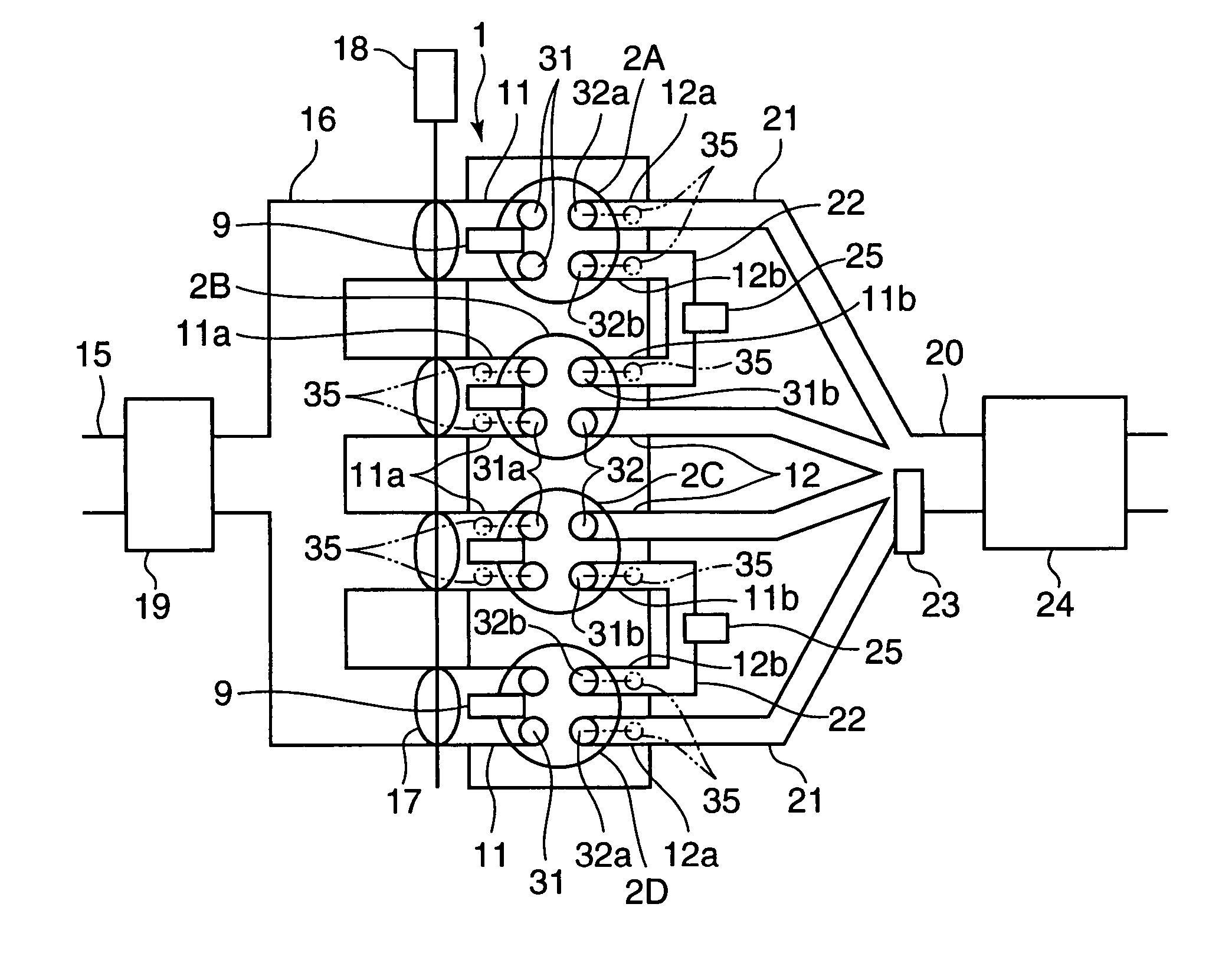
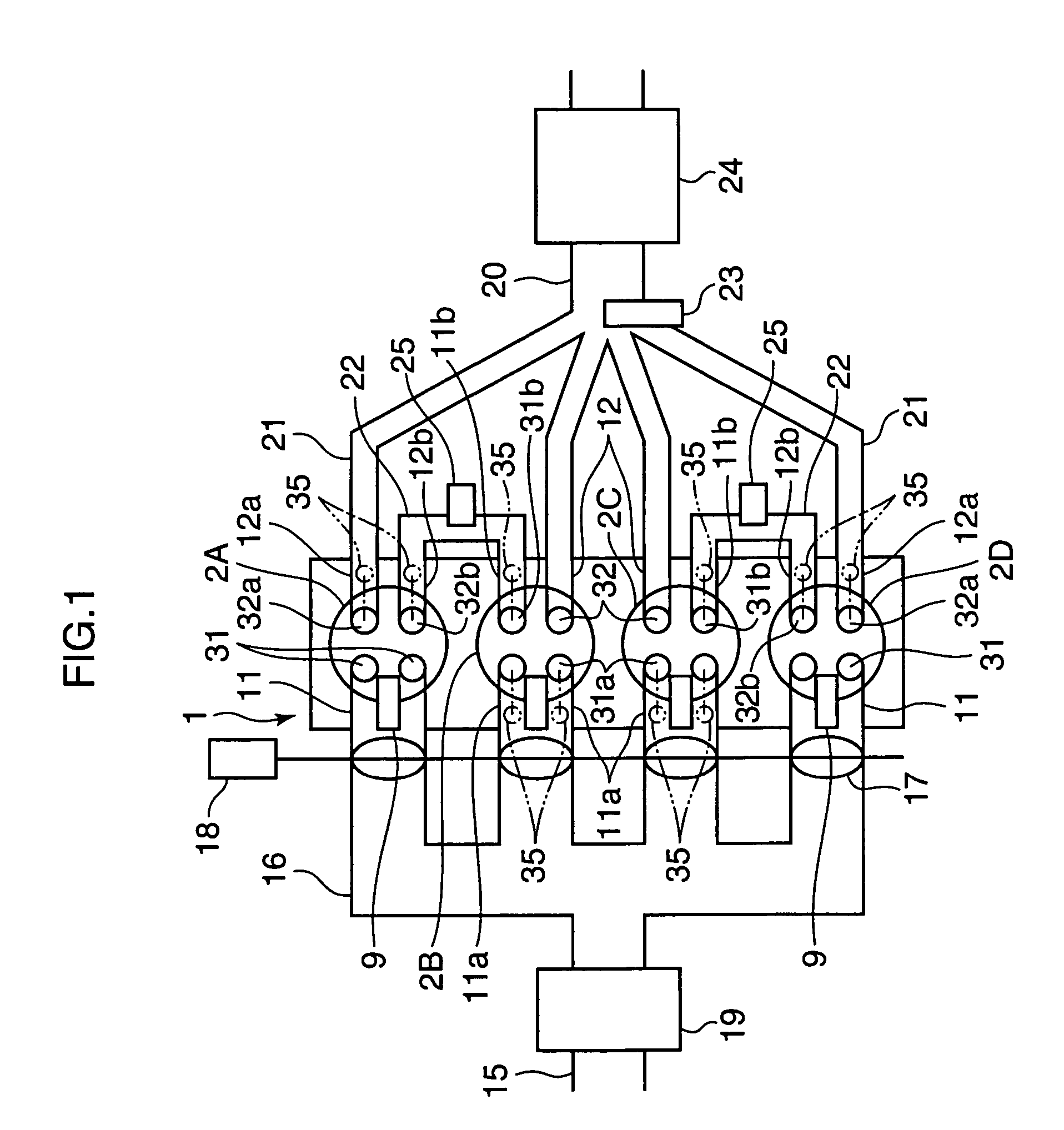
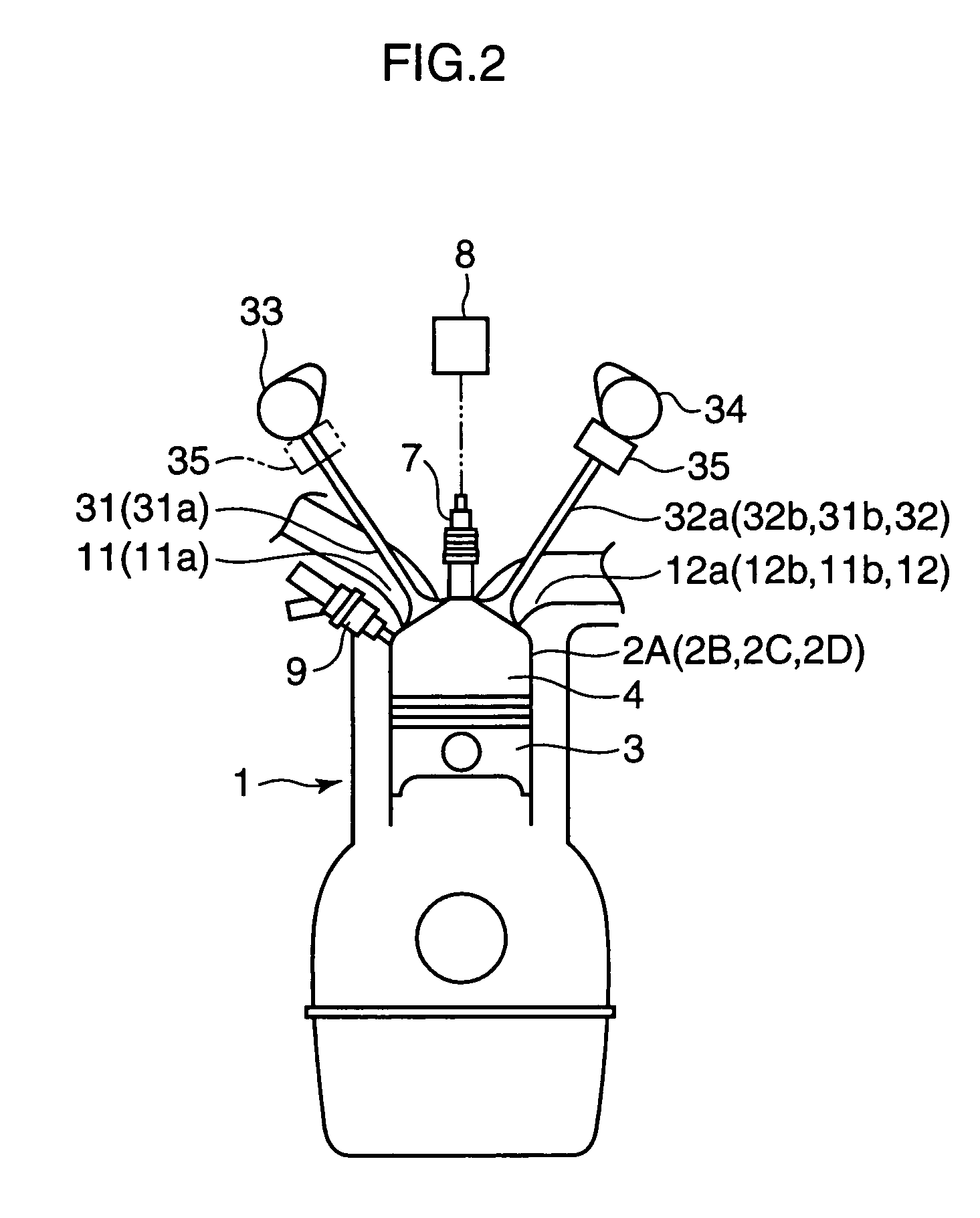
[0085]FIG. 1 shows the general construction of an engine provided with a control device according to an embodiment the invention, and FIG. 2 generally shows the construction of one cylinder of an engine body, intake and exhaust valves provided in the cylinder, etc. Referring to these Figures, the engine body 1 has a plurality of cylinders. Specifically, it has four cylinders designated 2A to 2D in the illustrated embodiment, with one each piston 3 fitted in the individual cylinders 2A–2D and a combustion chamber 4 formed above the piston 3.

[0086]There is provided a spark plug 7 at the top of the combustion chamber 4 in each cylinder 2 in such a way that a far end of the spark plug 7 is located inside the combustion chamber 4. The spark plug 7 is connected to an ignition circuit 8 which permits electronic control of ignition timing.

[0087]On one side of the combustion chamber 4 of each cylinder...


PUM


Abstract

The invention is intended to provide improved emission-cleaning performance by use of a three-way catalyst alone, without the need for a lean NOx catalyst, while ensuring a fuel economy improvement effect of lean burn operation. A multicylinder spark-ignition engine is constructed such that, in a pair of preceding and following cylinders whose exhaust and intake strokes overlap each other, burned gas discharged from the preceding cylinder (2A, 2D) which is currently in the exhaust stroke is introduced directly into the following cylinder (2B, 2C) which is currently in the intake stroke through an intercylinder gas channel (22) and gas discharged from only the following cylinder (2B, 2C) is led to an exhaust passage (20) provided with a three-way catalyst (24) in a low-load, low-speed operating range. Fuel supply to the individual cylinders is controlled in such a manner that combustion in the preceding cylinder (2A, 2D) is made under lean mixture conditions at an air-fuel ratio larger than the stoichiometric air-fuel ratio by a specific amount and combustion in the following cylinder (2B, 2C) is made under conditions of the stoichiometric air-fuel ratio created by supplying fuel to the burned gas introduced from the preceding cylinder (2A, 2D).

Description

TECHNICAL FIELD[0001]This invention relates to a control device for a spark-ignition engine. More particularly, the invention pertains to a device for controlling combustion state in individual cylinders to improve fuel economy and characteristics of emissions in a multicylinder engine.BACKGROUND ART[0002]There exists a conventionally known technique for achieving an improvement in fuel economy by performing combustion in a state of “lean” air-fuel ratio in which air-fuel mixture in individual cylinders of a spark-ignition engine is burnt at an air-fuel ratio larger than the stoichiometric air-fuel ratio. One example of this kind is shown in Japanese Unexamined Patent Publication No. H10-274085, which employs fuel injectors for injecting fuel directly into combustion chambers to cause stratified charge combustion by injecting fuel during a compression stroke in a low-speed, low-load range, for example, to thereby accomplish extremely lean mixture combustion.[0003]In this kind of eng...

Claims


Application Information

Patent Timeline
IPC IPC(8): F02B75/20F01L1/18F01L1/26F01L13/00F02B1/12F02B17/00F02B23/10F02B47/10F02B75/12F02B75/18F02D13/02F02D13/06F02D41/00F02D41/14F02D41/30F02D41/34F02F1/42F02M25/07F02P5/04F16N3/12
CPCF01L1/185F01L13/0005F01L13/0036F02B17/005F02B47/10F02B75/20F02D13/0215F02D13/0257F02D13/0261F02D13/06F02D41/0002F02D41/0057F02D41/0065F02D41/008F02D41/1475F02D41/3017F02D41/3029F02D41/3035F02F1/4214F02M25/0743F02M25/0748F02M25/0749F02M25/0752F02M25/0754F02P5/045F16N3/12F01L1/267Y02T10/18F01L2800/00F01L2800/06F02B1/12F02B23/104F02B2075/125F02B2075/1816F02B2275/18F02D13/0265F02D41/1454F02D41/1456F02D41/187F02D2013/0296F02D2041/0017Y02T10/123Y02T10/42Y02T10/47F02M26/01F02M26/37F02M26/42F02M26/43F02M26/47Y02T10/12Y02T10/40
Inventor HITOMI, MITSUOYAMAUCHI, TAKETOSHISHINYA, YOSHIYUKISUMIDA, KOUJIHAYASHI, TAKAYOSHI
Owner MAZDA MOTOR CORP
Why Eureka
Try Eureka