LPI engine system

a technology of engine system and liquefied petroleum gas, which is applied in the direction of electrical control, process and machine control, instruments, etc., can solve the problems of engine instability, engine power performance and fuel consumption ratio reduction, engine startability reduction, etc., to improve the fuel consumption ratio and power performance of a vehicle, and enhance the startability of the vehicle

Active Publication Date: 2007-02-27
HYUNDAI MOTOR CO LTD
View PDF10 Cites 31 Cited by
  • Summary
  • Abstract
  • Description
  • Claims
  • Application Information

AI Technical Summary

Benefits of technology

[0009]Embodiments of the present invention provides an LPI engine system which directly injects LPG fuel under high pressure into an intake system of an engine through an injector and is able to precisely control the injection rate of LPG fuel through the control of the injector, thus improving the fuel consumption ratio and the power performance of a vehicle, enhancing the startability of the vehicle in the winter, and making vehicle maintenance to address tar buildup after combustion unnecessary.

Problems solved by technology

However, in such a conventional LPG engine system, because it is difficult for an ECU (electronic control unit) to precisely control the injection rate of fuel, the startability of the engine is reduced in the winter, and the power performance and fuel consumption ratio of the engine are decreased.
As well, due to a problem of creation of tar when LPG fuel is burned, the engine is unstable when idling, and frequent engine stalling occurs.
However, the conventional LPI engine system is problematic in that, when the engine is in an ignition OFF state during a starting operation, pressure in a fuel system increases excessively due to the increased temperature of the fuel system, so that LPG fuel leaks into an intake system of the engine through the injector.
This problem is caused by the expansion in volume of LPG fuel due to the evaporation of LPG fuel, which has been in the liquid phase under high pressure, resulting from increased temperature of the fuel system when in the ignition OFF state.
That is, when the vehicle travels, the LPG fuel under high pressure is maintained in the liquefied state by natural cooling by outside air, but, when the engine enters the ignition OFF state when the vehicle is stopped, natural cooling of the fuel system by outside air cannot be performed, so that the fuel system is heated through thermal transfer by high-temperature conditions in the engine compartment.
As such, if LPG fuel leaks into the intake system of the engine during the ignition OFF state, when the engine is subsequently started, because LPG fuel, which is normally injected through the injector under the control of the ECU, is mixed with and burned along with the LPG fuel which has remained in the intake system after having leaked, there is a problem in that exhaust gas contains an excessive amount of hydrocarbon.

Method used


Image

  • LPI engine system
  • LPI engine system
  • LPI engine system

Examples


Embodiment Construction

[0016]Hereinafter, a preferred embodiment of the present invention will be described in detail with reference to the attached drawings.

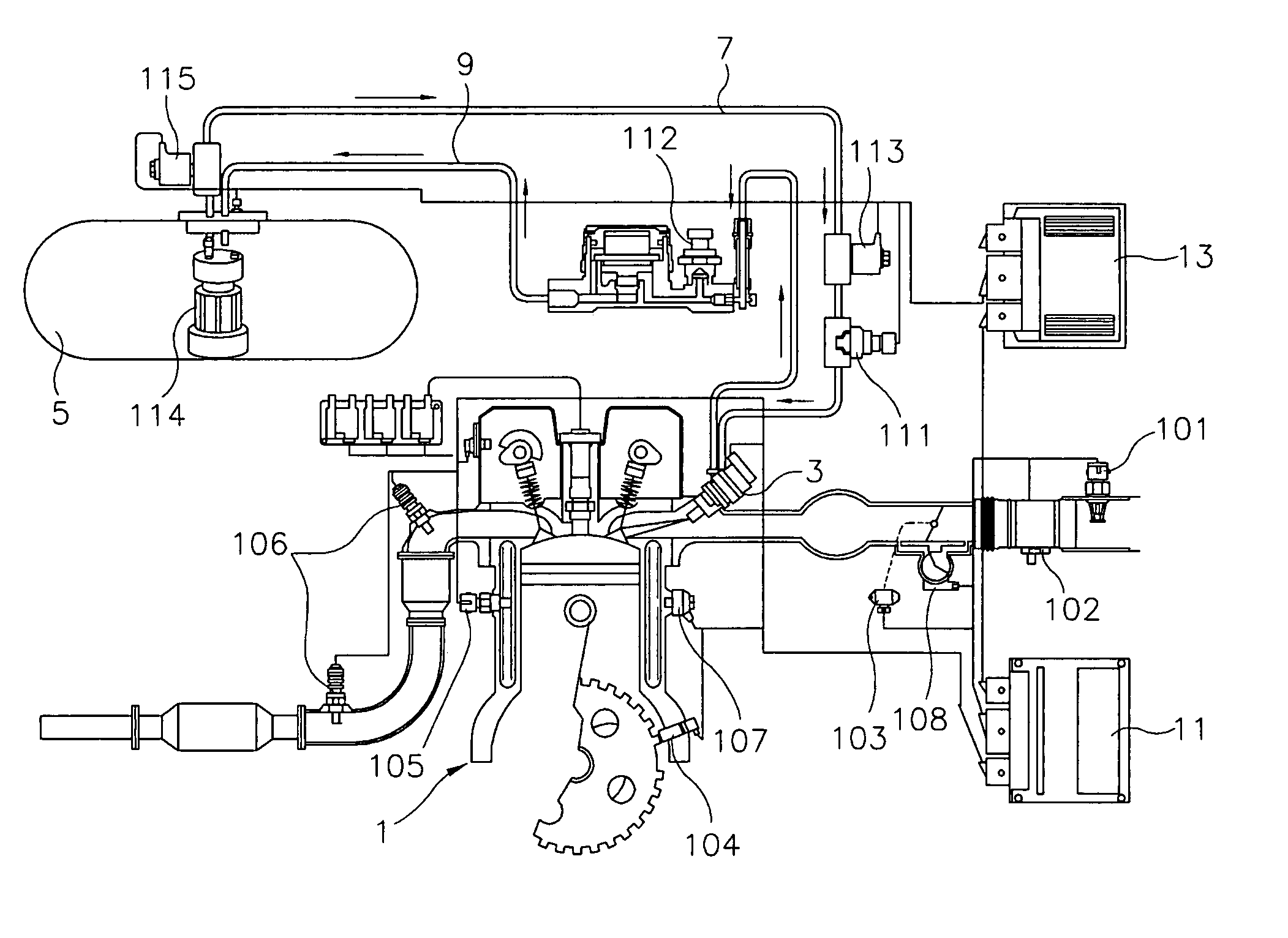
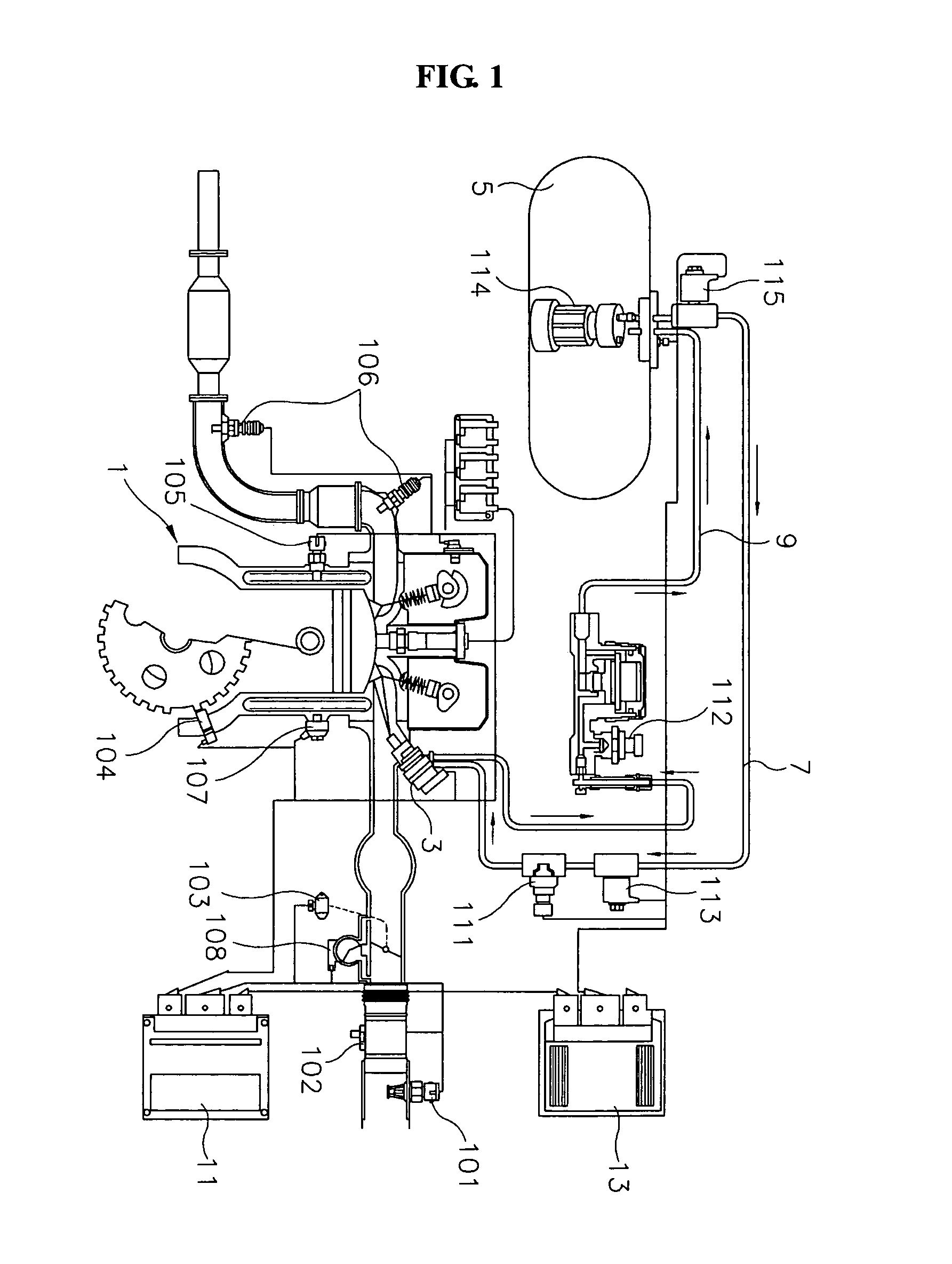
[0017]As shown in FIG. 1, an LPI (liquefied petroleum gas injection) engine system according to the preferred embodiment of the present invention includes an injector 3 which is provided in an intake system of an engine 1 to inject LPG (liquefied petroleum gas) fuel, and a fuel tank 5 which stores therein LPG fuel under high pressure to supply the LPG fuel to the injector 3. The LPI engine system further includes a supply line 7 and a recovery line 9 which are connected between the injector 3 and the fuel tank 5 so that LPG fuel is supplied and recovered through the supply line 7 and the recovery line 9. The LPI engine system further includes an EMS ECU (engine management system electronic control unit) 11 which appropriately controls the injection time and injection rate of LPG fuel injected through the injector 3, depending on traveling conditions,...


PUM


Abstract

Disclosed herein is an LPI engine system. The LPI engine system of the present invention directly injects LPG fuel under high pressure into an intake system of an engine through an injector and precisely controls the injection rate of LPG fuel through the control of the injector, thus improving the fuel consumption ratio and power performance of a vehicle, enhancing the startability of the vehicle in the winter, and making maintenance addressing the buildup of tar after combustion unnecessary. Furthermore, in the LPI engine system of the present invention, the injector, which adjusts the injection rate of LPG fuel into the intake system of the engine, includes a path shutoff part which functions to controls an LPG fuel injection path depending on an operational state of the engine, thus preventing LPG fuel from leaking into the intake system of the engine through the injector when the engine is in an ignition OFF state.

Description

CROSS-REFERENCE TO RELATED APPLICATIONS[0001]The present application is based on, and claims priority from, Korean Application Serial Number 10-2005-0080177, filed on Aug. 30, 2005, the disclosure of which is hereby incorporated by reference herein in its entirety.FIELD OF THE INVENTION[0002]The present invention relates to LPI (liquefied petroleum gas injection) engine systems and, more particularly, to an LPI engine system which directly injects LPG (liquefied petroleum gas) fuel under high pressure into an intake system of an engine through an injector.BACKGROUND OF THE INVENTION[0003]Generally, LPG engine systems are constructed such that LPG fuel, which has been stored in a fuel tank, is supplied into an engine after being evaporated by a mixer and a vaporizer. However, in such a conventional LPG engine system, because it is difficult for an ECU (electronic control unit) to precisely control the injection rate of fuel, the startability of the engine is reduced in the winter, an...

Claims


Application Information

Patent Timeline
Patent Type & Authority Patents(United States)
IPC IPC(8): F02B43/00G06F7/00
CPCF02B43/12F02D19/024F02D19/027F02M21/0254F02M21/0245F02M51/061Y02T10/32F02M21/0212F02M21/0242F02M21/026F02D19/025Y02T10/30F02M21/02F02D45/00
Inventor KIM, DEOK-RYOL
Owner HYUNDAI MOTOR CO LTD
Why Eureka
Try Eureka