
Trapezium or trapezometacarpal implant

a trapezometacarpal and trapezium technology, applied in the field of trapezal or trapezometacarpal implants, can solve the problems of deterioration of the implant, affecting the work of the surgeon, and affecting the function of the implant, so as to avoid excessive bone fragility, facilitate the work of the surgeon, and reduce the effect of deterioration

Inactive Publication Date: 2007-02-27
TORNIER SA SAINT ISMIER
View PDF7 Cites 92 Cited by
  • Summary
  • Abstract
  • Description
  • Claims
  • Application Information

AI Technical Summary

Benefits of technology

The present invention provides a trapezal or trapezo-metacarpal implant that is stable and easy to place. The implant has a stem and a head that can be inserted into the thumb metacarpus. The head is inclined relative to the stem, allowing for easy placement. The implant is stable due to the varus position of the head, which is in contact with the bone. The implant can be positioned without needing to cut into the bone, reducing the risk of complications. The head of the implant can be wide and have a large radius of curvature, making it easier to insert. The implant is stable and secure due to the inclination and offset of the head. The head is made of pyrocarbon, which has good friction with bone and reduces pain for the patient.

Problems solved by technology

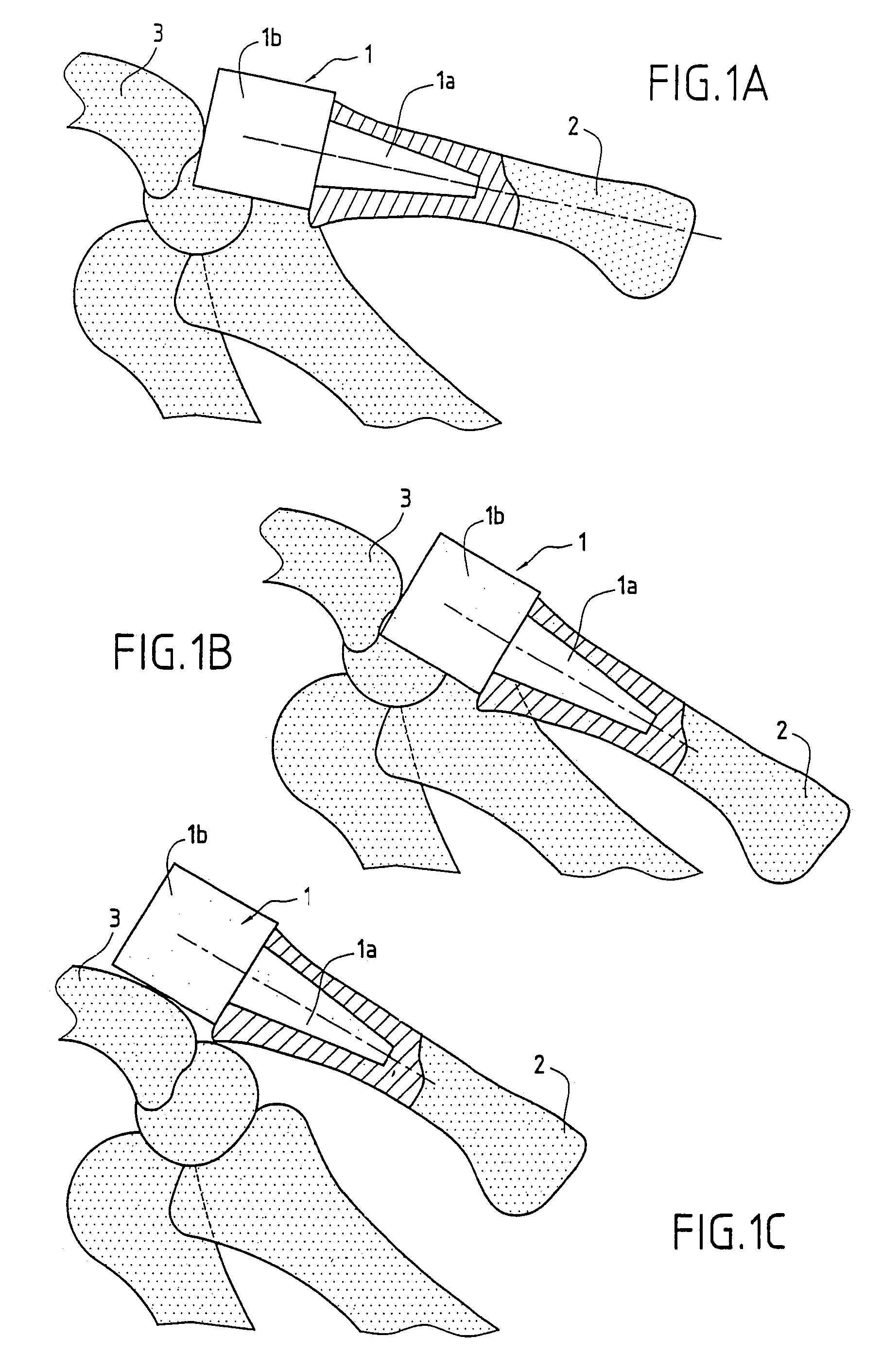
This implant has two principal drawbacks:the material from which it is made is unsuitable: silicone gives rise in certain patients to an allergy known as siliconite; moreover, because of its insufficient hardness, the silicone wears in contact with the adjacent bones, giving rise to deterioration of the implant;it is not stable and, in particular, has a tendency to dislocate, fully or partially; FIGS. 1A, 1B and 1C show a trapezal implant 1, whose stem 1a is mounted in the metacarpus 2 and the head 1b completely replaces the trapezium; in FIG. 1A, the implant is normally positioned relative to the adjacent bones and particularly relative to the scaphoid 3 with which it is in contact; FIG. 1B shows a typical configuration of partial dislocation of the implant during a pinching effort involving the thumb and at least one other finger of the hand; FIG. 1C shows a typical arrangement of full dislocation of the implant after such a pinching effort.
These techniques complicate the task of the surgeon and limit the mobility of the implant, causing trouble for the patient.
Nevertheless, fixing the implant in an inclined manner relative to the axis of the metacarpus requires providing an oblique hole in the shaft of the metacarpus, a delicate surgical operation to perform, which requires hollowing out the hard peripheral portion of the bone and which moreover renders this latter fragile.
In the same way as for the Swanson trapezal impant, the material from which these trapezo-metacarpal implants are made is unsuitable.
As previously explained, silicone is too soft.
As for titanium, it is too hard and wears the bones with which it is in contact.
It also makes the implant painful for the patient.

Method used


Image

  • Trapezium or trapezometacarpal implant
  • Trapezium or trapezometacarpal implant
  • Trapezium or trapezometacarpal implant

Examples


first embodiment

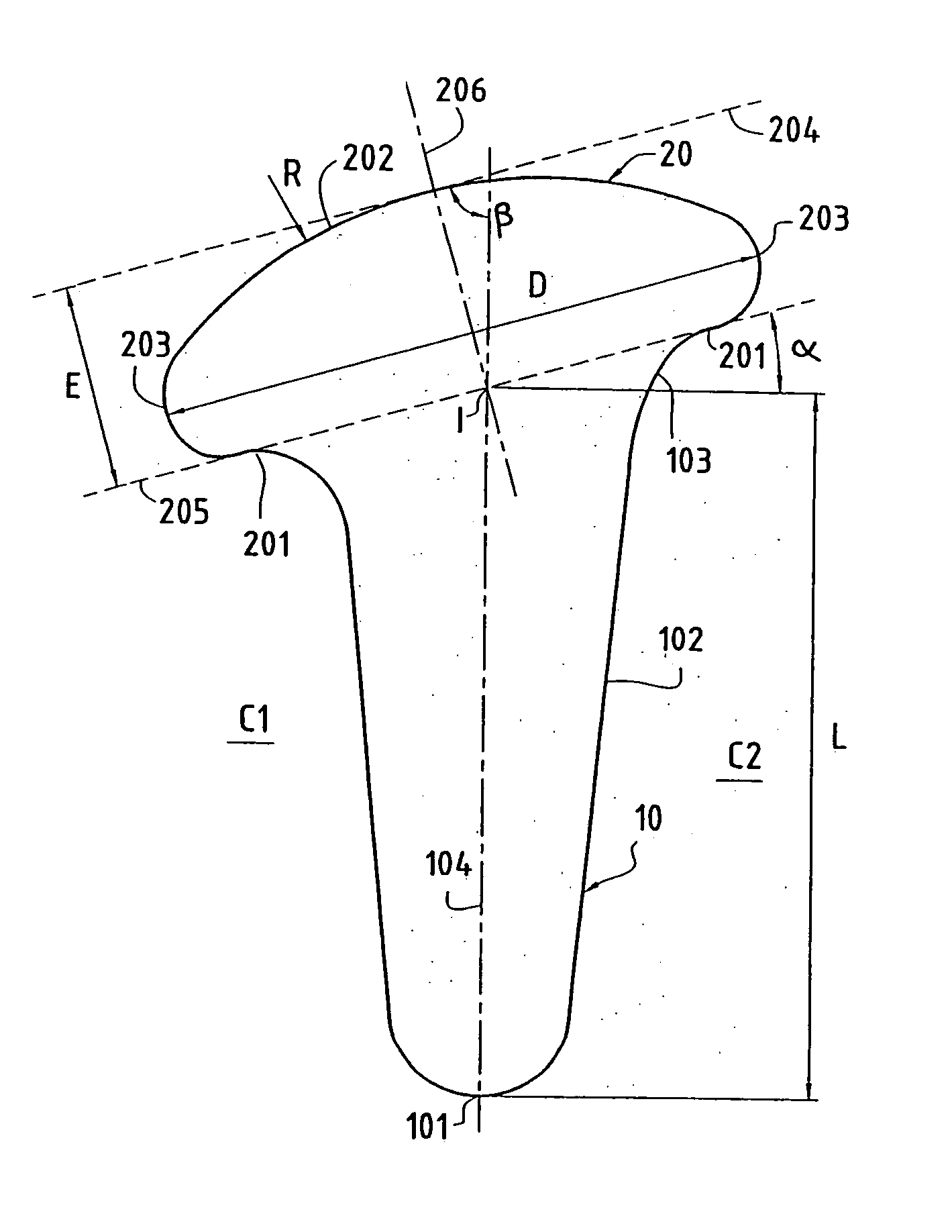
[0030]FIG. 4A shows an implant according to the invention.

[0031]The implant according to this first embodiment is a trapezo-metacarpal implant, in the general form of a nail. It comprises a stem 10 terminating, at a so-called proximal end, in a head 20 and whose opposite end, called the distal end, is constituted by a point 101.

[0032]Stem 10 is adapted to be inserted in the metacarpus of the thumb, and the head 20 to be disposed in a space obtained on the one hand by providing a cut or resection on the proximal end of the metacarpus and on the other hand by removing a portion of the trapezium facing the proximal portion of the metacarpus.

[0033]The head 20 has a flattened shape. Its longitudinal section is circular. Its surface is constituted by an annular and plane base 201 connected to the proximal end of the stem 10 and adapted to rest on the proximal portion of the metacarpus, a distal surface portion 202 opposite the base 201 and serving as a contact and friction surface with th...

second embodiment

[0044]FIG. 6 shows the implant according to the invention. The implant according to this second embodiment is a trapezo-metacarpal implant which differs from the implant according to the first embodiment essentially in that only the distal surface portion 202a is inclined relative to the stem 10a, and not the entire head 20a. Thus, the base 201a of the head 20a is perpendicular to the longitudinal axis 104a of the stem 10a. The connection portion 203a of the head 20a is thus higher on the side C2 of the implant where the angle between the distal surface portion 202a and the axis 104a is greater, than on the opposite side C1.

[0045]As in the first embodiment, the distal surface portion 202a is preferably offset relative to the axis 104a of the stem to the side C1.

[0046]The ratios indicated above between the diameter D of the head and the length L of the stem, and between the radius of curvature R of the distal surface portion of the head and the length L of the stem, also hold true fo...


PUM

PropertyMeasurementUnit
angleaaaaaaaaaa
angleaaaaaaaaaa
angle of inclinationaaaaaaaaaa

Abstract

The implant includes a stem terminating in a head. The stem is adapted to be inserted in the metacarpus of the thumb and the head to be disposed in a space obtained particularly by removing at least a portion of the trapezium. The surface of the head is constituted by a base connected to the stem and adapted to rest on the proximal end of the metacarpus, a distal surface portion opposite the base and serving as a contact surface with the bone located facing the proximal end of the metacarpus, and a connecting portion connecting the base and the distal surface portion of the head. The distal surface portion of the head is inclined relative to a longitudinal axis of the stem by a predetermined angle, such that, when the stem is mounted straight in the metacarpus, the distal surface portion of the head can be located in varus.

Description

FIELD OF THE INVENTION[0001]The present invention relates to a trapezal or a trapezo-metacarpal implant, comprising a stem terminating in a head. The stem is adapted to be inserted in the metacarpus of the thumb, and the head to be disposed in a space obtained particularly by removing all the trapezium, in the case of a trapezal implant, or a portion of the trapezium, in the case of a trapezo-metacarpal implant.[0002]The implant according to the invention can be used to treat rhizarthritis, a very frequent affliction consisting in an arthritis of the base of the thumb, essentially trapezo-metacarpal.STATE OF THE ART[0003]There exist several types of trapezal and trapezo-metacarpal implants.[0004]Among the most widely known are the so-called Swanson trapezal implant, constituted by a stem terminating in a head, the entirety made of silicone. In this implant, the head has a suitable size and shape to replace all the trapezium.[0005]This implant has two principal drawbacks:[0006]the ma...

Claims


Application Information

Patent Timeline
Patent Type & Authority Patents(United States)
IPC IPC(8): A61F2/42A61F2/00A61F2/30
CPCA61F2/4261A61F2/4241A61F2/30767A61F2310/00574A61F2002/30113A61F2002/30174A61F2002/3021A61F2002/30224A61F2002/30299A61F2002/30616A61F2002/30878A61F2002/4258A61F2002/4276A61F2230/0006A61F2230/0052A61F2230/0067A61F2230/0069A61F2230/0093A61F2310/00161A61F2310/00173A61F2002/30172
Inventor HASSLER, MICHELREAL, CECILEPEQUIGNOT, JEAN-PIERREALLIEU, YVES
Owner TORNIER SA SAINT ISMIER
Learn More