Direct conversion receiver for calibrating phase and gain mismatch

a receiver and gain mismatch technology, applied in the field of direct conversion rf signal receivers, can solve the problems of phase mismatch, gain mismatch in the output signal of the mixer, and increase the error rate of the received signal, so as to minimize the distortion of the converted radio frequency rf signal

Active Publication Date: 2007-02-27
SAMSUNG ELECTRONICS CO LTD
View PDF12 Cites 8 Cited by
  • Summary
  • Abstract
  • Description
  • Claims
  • Application Information

AI Technical Summary

Benefits of technology

[0010]The present invention provides a direct conversion receiver (DCR) that minimizes distortion of a convert...

Problems solved by technology

However, the phase difference of the first and second location oscillation signals (OS1, OS2) is actually 90±φ (causing a phase mismatch.
Also, a gain mismatch occurs in the output signals of the mixers.
If the phase and gain mismatch occurs in the DCR, as described above, the erro...

Method used


Image

  • Direct conversion receiver for calibrating phase and gain mismatch
  • Direct conversion receiver for calibrating phase and gain mismatch
  • Direct conversion receiver for calibrating phase and gain mismatch

Examples


Embodiment Construction

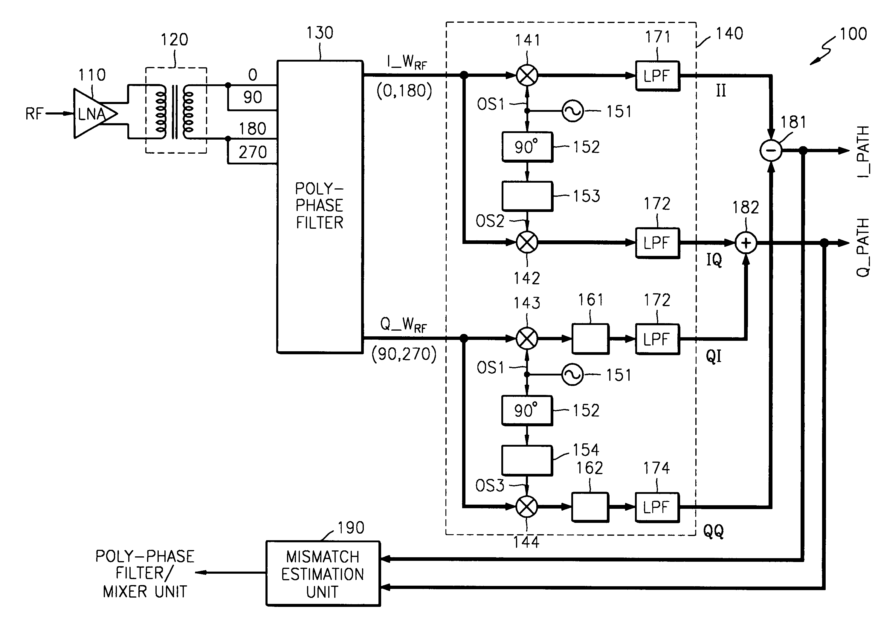
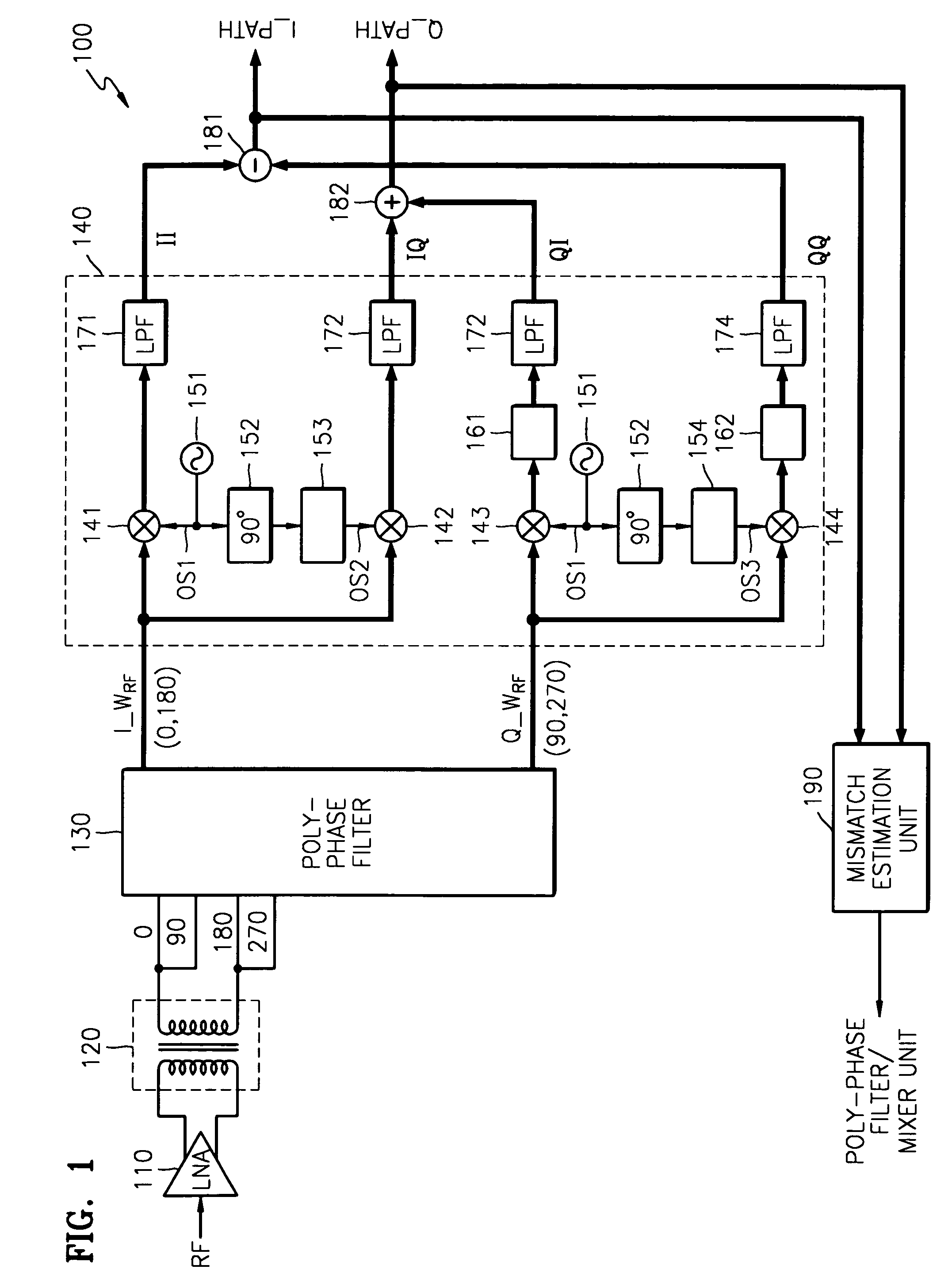
[0026]Referring to FIG. 1, the DCR according to a preferred embodiment of the present invention comprises a low noise amplifier 110, a transformer 120, a poly-phase filter 130, a mixer unit 140, a subtracter 181, an adder 182, and a mismatch estimation unit 190.

[0027]The low noise amplifier 110 receives and amplifies an RF signal. The transformer 120 converts the amplified RF signal into differential signals of 0° and 180°.

[0028]The poly-phase filter 130 receives the differential signals of 0° and 180° as inputs and outputs signals having phases of 0°, 90°, 180°, and 270°. The signals of 0° and 180°, respectively, are input into the 90° and 270° inputs of the poly-phase filter 130. The poly-phase filter 130 receives differential signals of 0° and 180° and outputs an in-phase (0° and 180°) differential signal (I_WRF), and a quadrature-phase (90° and 270°) differential signal (Q_WRF).

[0029]The mixer unit 140 comprises in-phase first and second mixers 141 and 142, quadrature-phase thir...


PUM


Abstract

A direct conversion receiver (DCR) calibrated for phase and gain mismatch is provided. The DCR comprises a poly-phase filter that generates mismatched in-phase and quadrature-phase differential signals; the in-phase differential signal is mixed with first and second local oscillation signals; the quadrature-phase differential signal is mixed with third and fourth local oscillation signals; the first and second local oscillation signals have a first adjustable phase mismatch, and the third and fourth oscillation signals have a second adjustable phase mismatch; A mismatch estimation unit (MEU) estimates the entire phase/gain mismatch (signal distortion) of the DCR, The first and second adjustable phase mismatches are adjusted so that the signal distortion of the DCR, as estimated by the MEU is minimized. Thereafter, reduced-component DCRs (without an MEU), calibrated for the mismatches of a poly-phase filter, may be mass produced.

Description

BACKGROUND OF THE INVENTION[0001]1. Field of the Invention[0002]The present invention relates to a radio frequency (RF) signal receiver, and more particularly, to a direct conversion RF signal receiver.[0003]2. Description of the Related Art[0004]A direct conversion method is a method by which a signal in an RF band is down-converted into a baseband signal by mixing once the RF signal with a local oscillation signal. That is, the RF band signal is directly converted into a baseband signal, not converted into an intermediate frequency (IF) band signal and then into a baseband signal. In general, the former is referred to as a heterodyne method, while the latter is referred to as a direct conversion method.[0005]FIG. 7 is a diagram of a conventional direct conversion receiver (hereinafter referred to as a DCR). When the conventional DCR receives an RF signal, a low noise amplifier 110 amplifies the RF signal and a transformer 120 converts the amplified RF signal into a differential si...

Claims


Application Information

Patent Timeline
IPC IPC(8): H04B1/26H03D3/00H04B1/10H04B1/30
CPCH04B1/30H03D3/009H04B1/10
Inventor KIM, YOUNG-JIN
Owner SAMSUNG ELECTRONICS CO LTD
Why Eureka
Try Eureka