Illumination optical system and projector comprising the same

a technology of optical system and projector, which is applied in the direction of identification means, instruments, polarising elements, etc., can solve the problems of image becoming too glaring to see, significant limitation of design freedom of projection lens, and increase the size of projection lens, so as to achieve the effect of enhancing the brightness of optical equipment and not degrading the design freedom of other optical systems

Inactive Publication Date: 2007-03-06
SEIKO EPSON CORP
View PDF22 Cites 46 Cited by
  • Summary
  • Abstract
  • Description
  • Claims
  • Application Information

AI Technical Summary

Benefits of technology

[0010]The object of the present invention is thus to provide an illumination optical system capable of maintaining higher brightness of optical equipment and adjusting the brightness as required without degrading design freedom of other optical systems such as a projection optical system and a projector provided with the same.
[0011]An illumination optical system comprising: a light source; a beam splitting element including a plurality of lenses that splits light emitted from the light source into a plurality of sub-beams; a polarization conversion element including a polarization beam splitter array that splits each of the plurality of sub-beams into two types of polarized light, the polarization beam splitter array having a plurality of polarization splitting films and reflective films which are alternately arranged, and a phase element disposed on the emitting surface side of the polarization beam splitter array to align the light polarization directions of the two types of polarized light; and a light shielding member that adjusts a quantity of incident light on the polarization splitting films, the light shielding member being provided between the beam splitting element and the polarization beam splitter array. Consequently, the quantity of the incident light on an object to be illuminated can be adjusted without limiting design freedom of other optical systems such as a projection optical system. In addition, appropriate adjustment of the quantity of the incident light contributes to a longer life of equipment to be illuminated such as an electro-optical device illuminated by this illumination optical system.
[0012]The light shielding member may be a light shielding plate provided with a plurality of light shielding portions and apertures corresponding to the polarization splitting films and reflective films and is movably disposed along the polarization conversion element. Also, the light shielding member may be constituted by a plurality of parallel light shielding plates to adjust the quantity of the incident light by moving any ones thereof. By using these members, the quantity of the incident light can be easily adjusted. In the above case, when a plurality of light shielding plates are disposed corresponding to the plurality of polarization splitting films, respectively, the quantity of the incident light can be adjusted for each polarization splitting film, thereby improving precision of the adjustment.
[0013]The light shielding member may be a variable diaphragm which arbitrarily reduces the quantity of the incident light on the polarization splitting films constituting the polarization conversion element. In this case, light transmitting portions of the variable diaphragm are formed as slits and the quantity of the incident light on the polarization splitting films can be reduced by changing widths of the slits.
[0014]This variable diaphragm can also adjust a quantity of incident light on an object to be illuminated without limiting design freedom of other optical systems such as a projection optical system, thereby contributing to a longer life of equipment to be illuminated such as an electro-optical device illuminated by this illumination optical system.
[0015]The light shielding member is preferably composed of metallic material having an optical reflectance of 80% or more. Since heat absorption in the light shielding member is retarded by using such a material, a light shielding member or diaphragm having excellent heat resistance can be obtained even under high brightness conditions.

Problems solved by technology

However, when an image is projected in a size smaller than preset size by utilizing such a device having higher brightness, unnecessarily excessive light is projected on a projection screen so that the image becomes too glaring to see.
As a result, however, design freedom of the projection lens is significantly limited, that is, the size of the projection lens is increased and the types thereof are limited and so on.

Method used


Image

  • Illumination optical system and projector comprising the same
  • Illumination optical system and projector comprising the same
  • Illumination optical system and projector comprising the same

Examples


Embodiment Construction

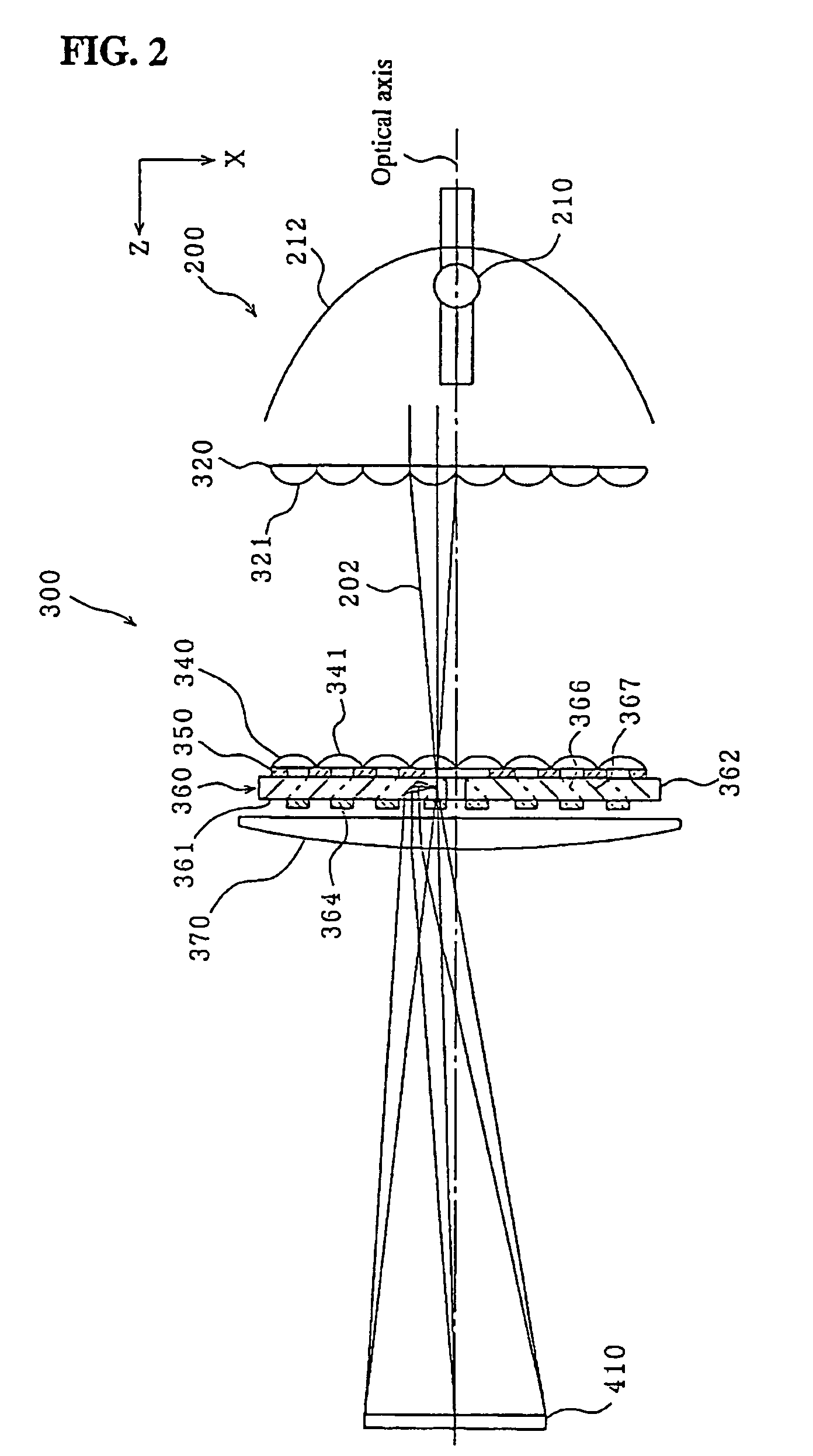
[0032]Now, embodiments of the present invention will be explained below by way of example. In the following explanations, the traveling direction of the light is defined as a z-direction, the direction of 12 o'clock with respect to the z-direction is defined as a ydirection, and the direction of 3 o'clock with respect to the z-direction is defined as an x-direction, unless otherwise specified.

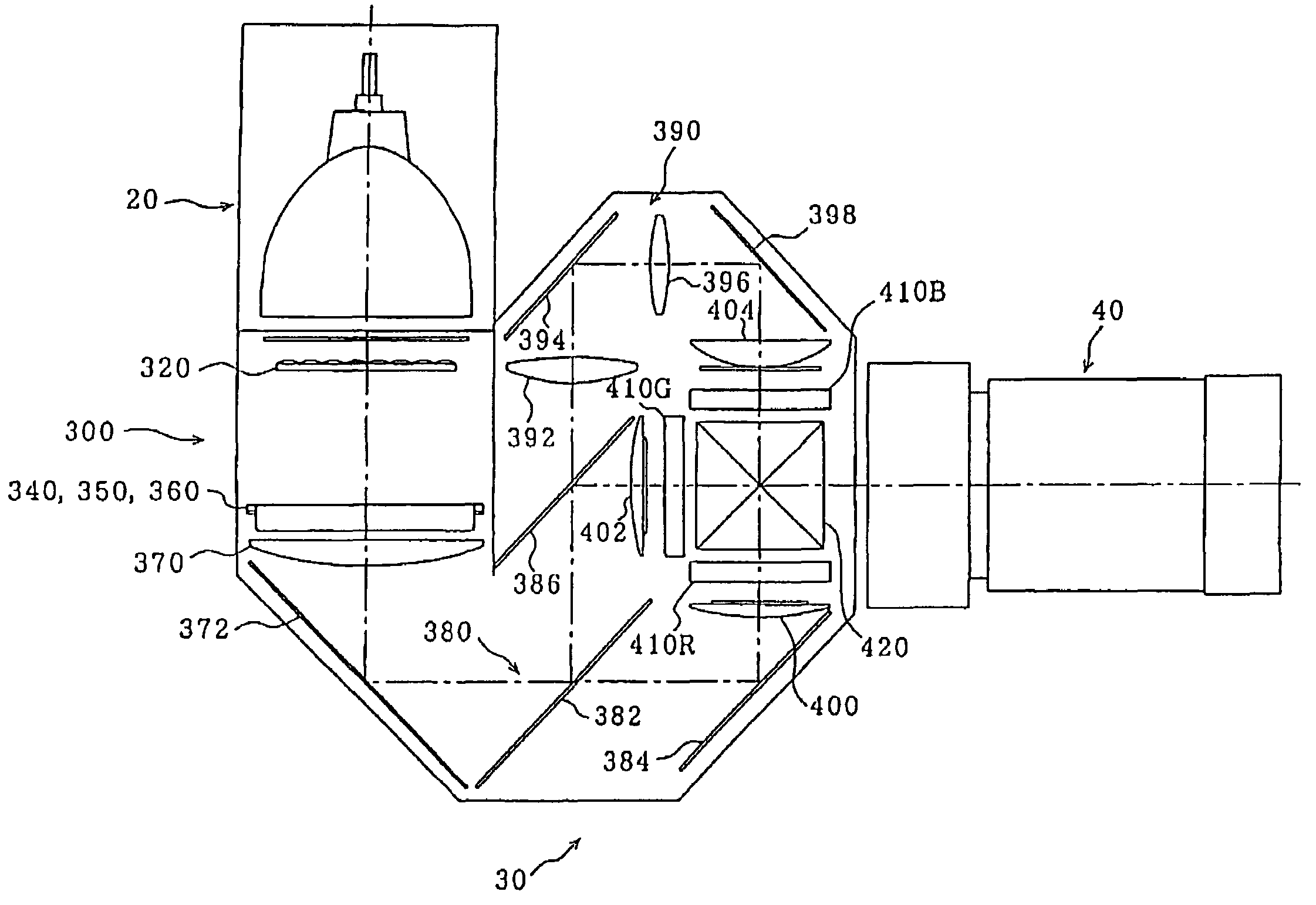
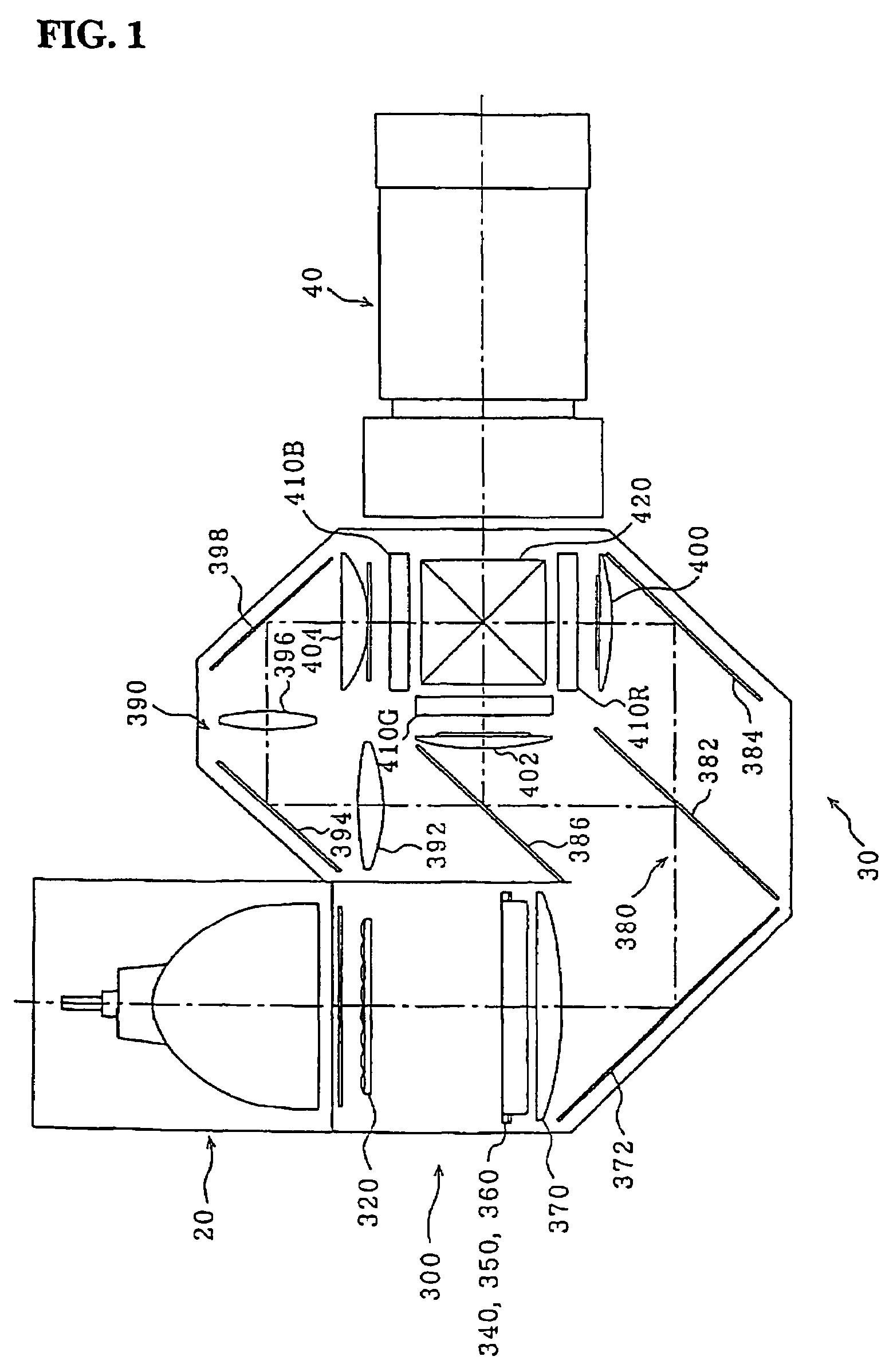
[0033]FIG. 1 is a schematic plan view showing the configuration of an illumination optical system incorporated into a projector according to an embodiment of the present invention. The optical system includes three main portions: a light source unit 20, an optical unit 30, and a projection lens 40. The optical unit 30 is provided with an integrator optical system 300 described later, a color beam splitting optical system 380 having dichroic mirrors 382, 386 and a reflective mirror 384, a relay optical system 390 having an incident lens 392, a relay lens 396 and reflective mirrors 394, 398. The ...


PUM

PropertyMeasurementUnit
optical reflectanceaaaaaaaaaa
aspect ratioaaaaaaaaaa
reflectanceaaaaaaaaaa

Abstract

Brightness of optical equipment can be adjusted as required. An illumination optical system includes a light source, a lens array composed of a plurality of lenses for splitting light emitted from the light source into a plurality of sub-beams, and a polarization conversion element for adjusting the light polarization directions. The illumination optical system further includes a light shielding member between the lens array and the polarization conversion element to adjust the quantity of incident light on polarization splitting films provided in the polarization conversion element.

Description

BACKGROUND OF THE INVENTION[0001]1. Field of the Invention[0002]The present invention relates to an illumination optical system and a projector provided with the same.[0003]2. Description of the Related Art[0004]FIG. 11 is a perspective view showing the appearance of a typical projector. Here, a rectangular parallelepiped projector 501 includes an upper case 503 which defines the upper surface thereof and is provided with operating buttons 502 disposed thereon, a lower case 504 which defines the lower surface of the projector 501 and a front case 505 which defines the front surface of the projector 501. There is a projection lens 506, the front end portion of which protrudes from the front case 505.[0005]A known optical system in such a projector is constituted, for example, as shown in FIG. 12.[0006]That is, the projector is provided with an illumination optical system 520 for making an illumination distribution of light from a light source 510 uniform and making the light incident...

Claims


Application Information

Patent Timeline
Patent Type & Authority Patents(United States)
IPC IPC(8): G03B21/00G03B21/14G02B5/00G02B5/30G02B19/00G02B27/28G02F1/13G02F1/1335G03B21/20G03B33/12G09F9/00H04N9/31
CPCG02B27/283G03B33/12G03B21/2073H04N9/3167H04N9/3197H04N9/3105G02F1/13362G03B21/20
Inventor AKIYAMA, KOICHI
Owner SEIKO EPSON CORP
Why Eureka
Try Eureka