Fan inlet and housing for a centrifugal blower whose impeller has forward curved fan blades

a centrifugal blower and impeller technology, applied in the direction of machines/engines, stators, liquid fuel engines, etc., can solve the problems of low efficiency, high energy consumption, and inability to provide desirable replacement parts, so as to efficiently direct the incoming airflow

Active Publication Date: 2007-03-06
TRANE INT INC
View PDF18 Cites 16 Cited by
  • Summary
  • Abstract
  • Description
  • Claims
  • Application Information

AI Technical Summary

Benefits of technology

[0011]A primary object of the invention is to reduce the low frequency noise and improve the efficiency of a forward curved fan (a centrifugal blower with forward curved fan blades).
[0013]Another object of some embodiments is to provide a forward curved fan with an inlet shroud that has a recurved surface for minimizing flow vortices near the open axial end of the impeller.
[0017]Another object of some embodiments is to size and position multiple curved surfaces of an inlet shroud in such a way as to improve the operating characteristics of a forward curved fan.
[0024]One or more of these and / or other objects of the invention are provided by a centrifugal blower that includes a housing containing an impeller with forward curved fan blades, wherein the housing includes an inlet shroud with a recurved surface that efficiently directs the incoming airflow into the impeller.

Problems solved by technology

Simply replacing the inlet shroud of any forward curved blade with that of a backward inclined blade will not necessarily provide desirable results.
Lower efficiency not only increases operating costs, but can also create high energy, low frequency noise, which is particularly difficult to suppress.

Method used


Image

  • Fan inlet and housing for a centrifugal blower whose impeller has forward curved fan blades
  • Fan inlet and housing for a centrifugal blower whose impeller has forward curved fan blades
  • Fan inlet and housing for a centrifugal blower whose impeller has forward curved fan blades

Examples


Embodiment Construction

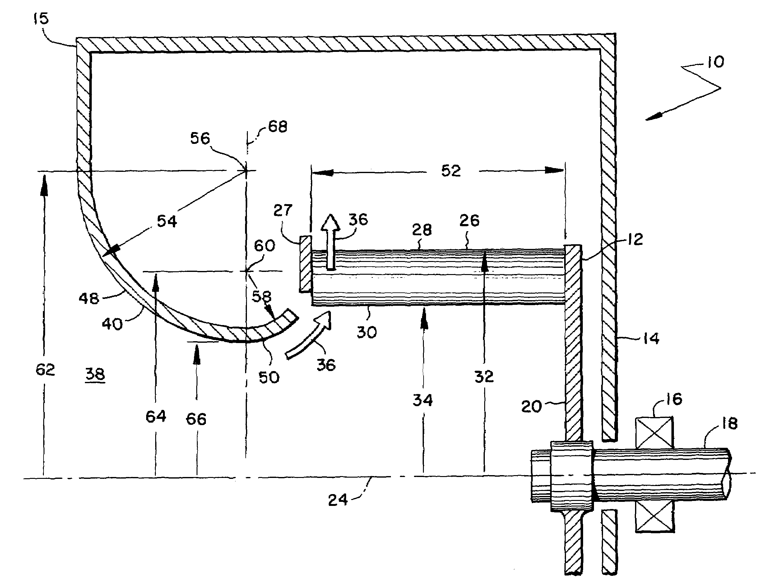
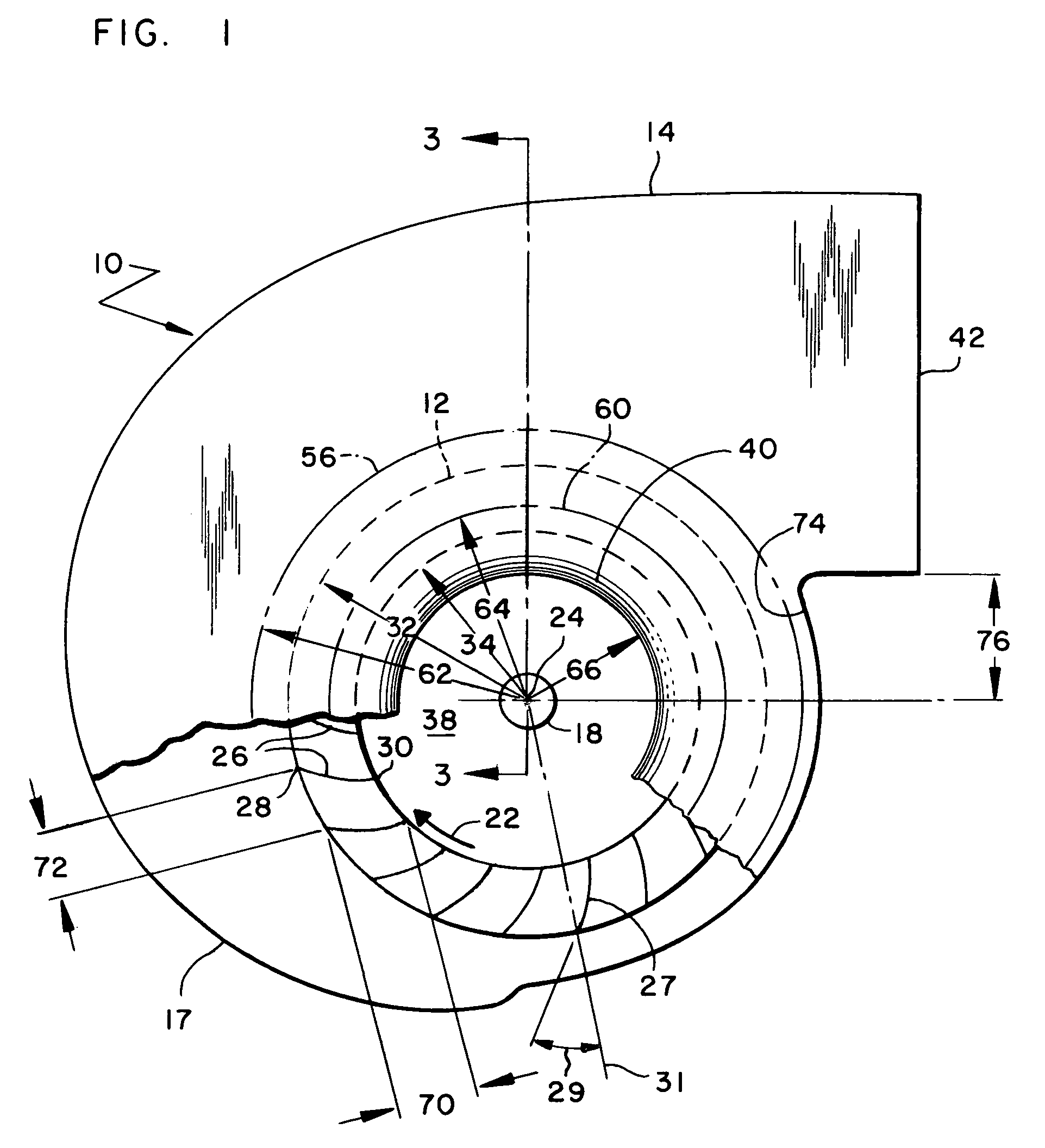
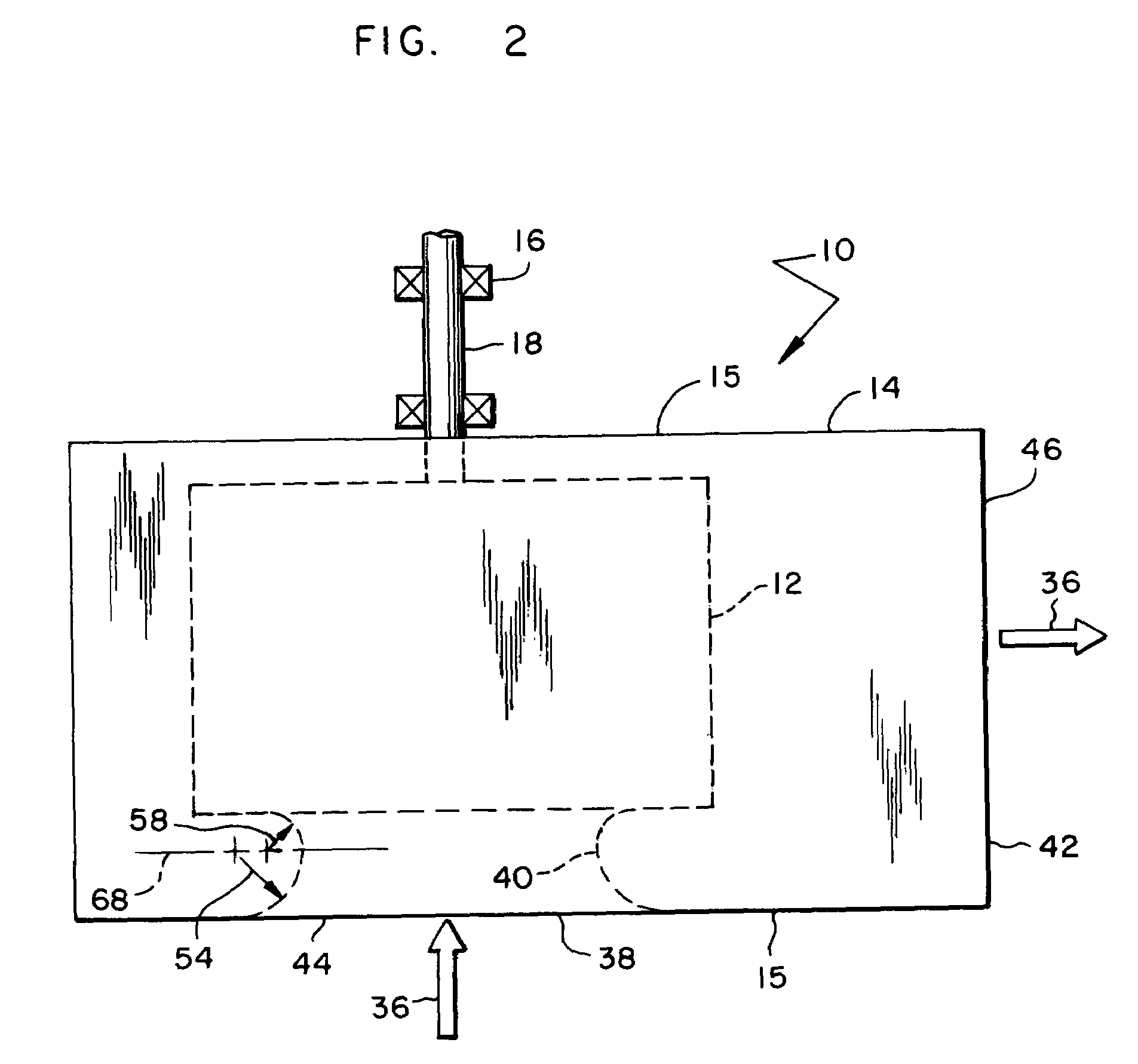
[0028]FIGS. 1–3 show a centrifugal fan or blower 10 that includes an impeller 12 mounted for rotation within a volute or scroll shaped housing 14 including first and second end walls 15 and a scroll wall 17 having at least a portion with a continuously increasing radius relative to a rotational axis 24. One or more bearings 16 support a shaft 18 that is connected to a circular hub plate 20 of impeller 12 such that a motor or some other drive mechanism can rotate impeller 12 in a forward rotational direction 22 about the rotational axis 24.

[0029]Impeller 12 comprises a plurality of forward curved fan blades 26 axially interposed between hub plate 20 and an annular shroud plate 27. The term, “forward curved” refers to a fan blade having a surface near its outer trailing edge that leans into the blade's direction of travel. Each blade 26, for example, has a surface adjacent a trailing outer edge 28 that lies at a positive angle 29 relative to a radial centerline 31 extending from axis ...


PUM


Abstract

A centrifugal blower with forward curved fan blades includes an inlet shroud whose shape is specifically designed for creating a smooth incoming airflow pattern that leads into the inner leading edges of the fan blades. The inlet shroud has first and second curved surfaces, wherein the centers of curvature of the two surfaces lie in the same plane, and the center of curvature as well as the radius of curvature of one curved surface is greater than that of the other. At least one center of curvature lies beyond the outer diameter of the impeller, and at least one center of curvature lies beyond the impeller's inner diameter, wherein the impeller's inner diameter is defined by the inner leading edges of the fan blades. Performance benefits are achieved when a forward curved blower with such an inlet shroud operates with a flow coefficient of between 9 and 52.

Description

BACKGROUND OF THE INVENTION [0001]1. Field of the Invention[0002]The subject invention generally pertains to centrifugal blowers whose impellers have forward curved fan blades and more specifically to a fan inlet shroud for such a blower.[0003]2. Description of Related Art[0004]Centrifugal blowers, such as those disclosed in U.S. Pat. Nos. 5,570,996; 5,558,499; 3,627,440; 3,307,776; 3,217,976; 2,981,461; 2,951,630; 2,798,658; 2,727,680; 3,221,983 and 1,862,523, are fans that draw air in an axial direction and discharge the air radially relative to the rotational axis of the blower's impeller. To create such a flow pattern, centrifugal blowers often include a scroll shaped housing or volute that contains an impeller of a particular design.[0005]There are countless centrifugal impeller designs such as impellers with backward inclined fan blades, forward curve fan blades, radial or flat paddlewheel blades, airfoil or streamlined blades, and various combinations thereof. The present inv...

Claims


Application Information

Patent Timeline
Patent Type & Authority Patents(United States)
IPC IPC(8): F04D29/44
CPCF04D29/4226F04D29/4213
Inventor SMILEY, III, WILLIAM A.MEHTA, PRAVINCHANDRA C.
Owner TRANE INT INC
Why Eureka
Try Eureka