
Blood component collection method

a technology of blood component and collection method, which is applied in the direction of centrifuges, multi-stage water/sewage treatment, separation processes, etc., can solve the problems of degrading the quality of the platelet product, increasing the number of leukocytes mixed in the platelet product, and increasing the risk of fever attack, etc., to achieve the effect of high quality

Inactive Publication Date: 2007-03-06
TERUMO KK
View PDF8 Cites 35 Cited by
  • Summary
  • Abstract
  • Description
  • Claims
  • Application Information

AI Technical Summary

Benefits of technology

The present invention provides a blood component collection system that can collect high-quality blood components. The system includes a centrifugal separator, containers for temporarily reserving blood components, a cell separating filter, and a control means for controlling the action of channel open / close means. The system can adjust the amount of blood component to be collected based on the fed amount of a second blood component. The second blood component can be fed from a third container and can be combined with the first blood component. The system can also include a leukoreduction filter for separating or reducing cells from the first blood component. The technical effects of the invention include improved quality of blood components and efficient blood component collection.

Problems solved by technology

However, according to the above method, when a large number of platelets is needed, the number of leukocyte (white blood cells) mixed in a platelet product increases.
This leads to an increase in the risk of an attack of fever, alloimmunization, virus infection, or the like.
This poses a problem that the quality of the platelet product is degraded.

Method used


Image

  • Blood component collection method
  • Blood component collection method
  • Blood component collection method

Examples


example

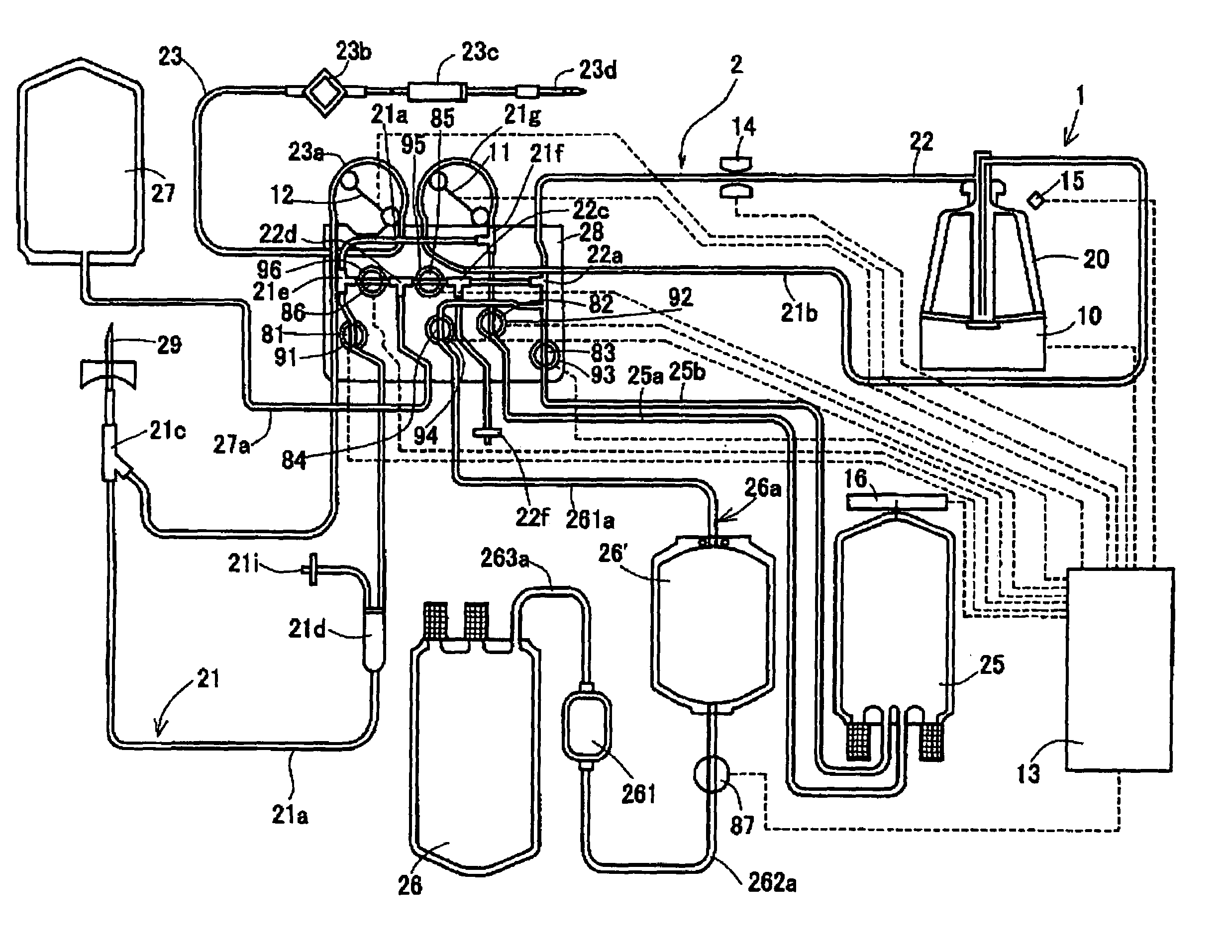
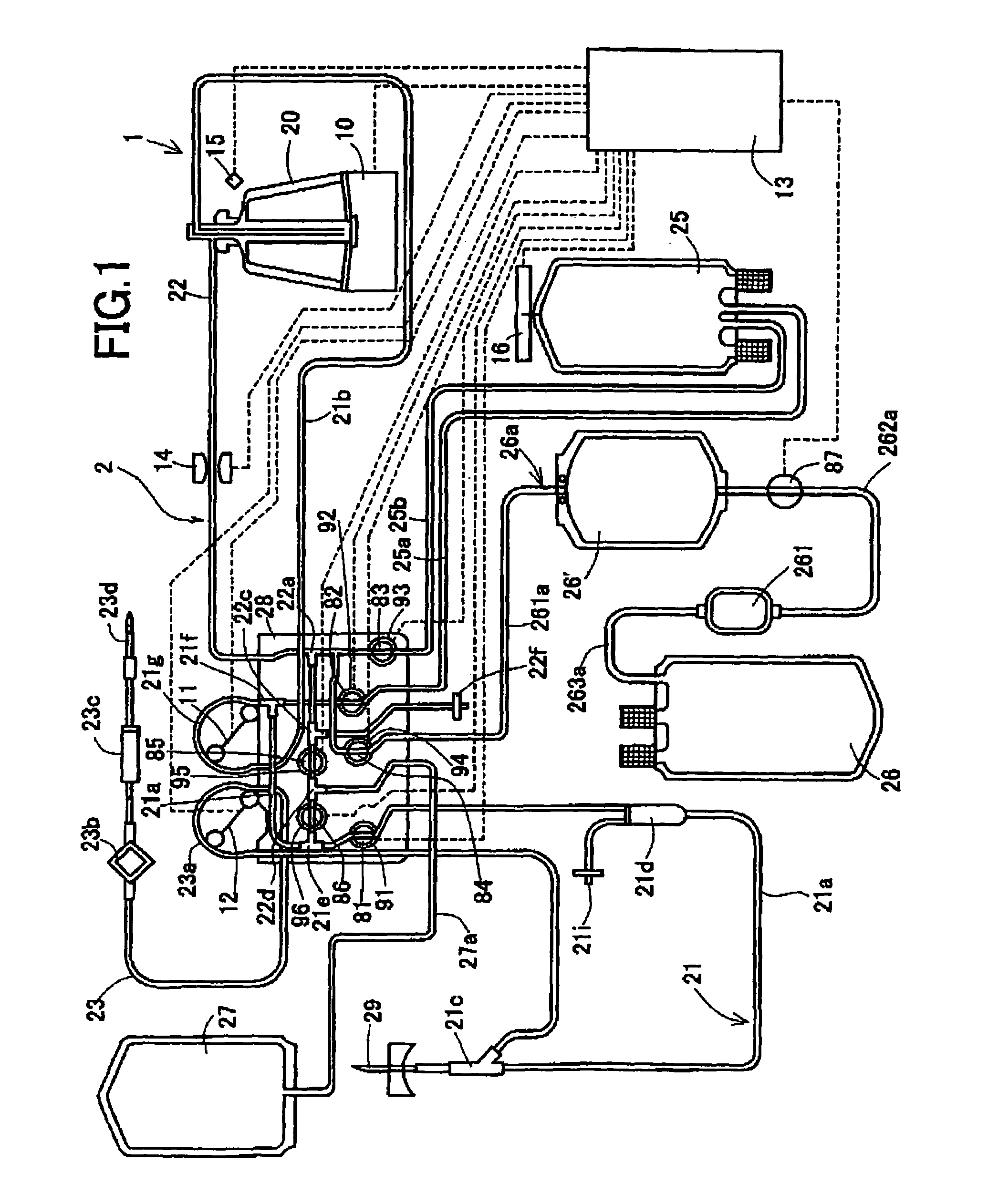
[0265]A blood component collection circuit (Terumo Leukoreductive Apheresis set (with a leukoreduction filter) manufactured by Terumo Corp.), and a blood component collection system (Terumo Apheresis machine AC-550 manufactured by Terumo Corp.) were remodeled in order to construct the blood component collection system shown in FIG. 1. The system was used to perform platelet collection (four times) by executing the aforesaid processes.

[0266]Moreover, the conditions for each of the processes to be executed in order to achieve platelet collection will be listed below. The interface between blood components to be detected was the interface between a layer of plasma and a buffy coat layer.

[First Plasma Collection Process]

[0267]Rotor: rotational frequency: 4800 rpm[0268]First fluid feeder pump: rotating speed: 60 mL / min[0269]Condition for terminating the process:[0270]A collected amount should reach 30 g.

[Constant-speed Plasma Circulation Process][0271]Rotor: rotational frequency: 4800 rp...


PUM

PropertyMeasurementUnit
thicknessaaaaaaaaaa
thicknessaaaaaaaaaa
volumeaaaaaaaaaa

Abstract

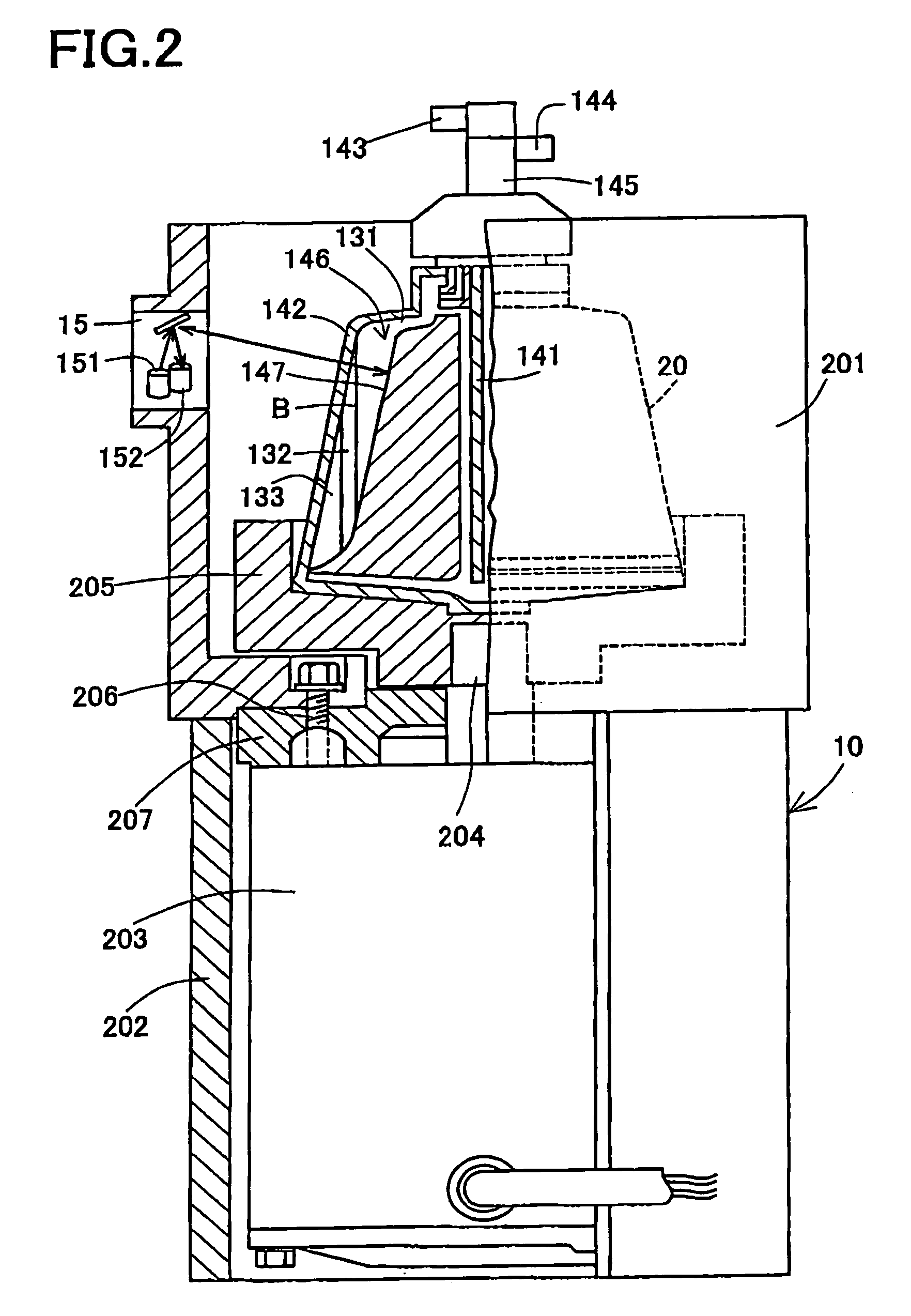
An object is to provide a blood component collection system capable of collecting a desired blood component of high quality. A blood component collection system 1 comprises a centrifugal separator 20 centrifuging blood into a plurality of components, first line 21 for feeding the blood to the centrifugal separator 20, a second line 22 for releasing the blood component from the centrifugal separator 20, a temporary reservoir bag 26′ for temporarily reserving the platelet concentrate, a leukoreduction filter 261 for separating and reducing leukocyte from the platelet concentrate, and a platelet collection bag 26 for reserving the platelet concentrate having passed through the leukoreduction filter 261. The blood component collection system 1 is constructed to feed the platelet concentrate in the temporary reservoir bag 26′ to the platelet collection bag 26 through the leukoreduction filter 261, and then, feed plasma and collect the platelet remaining in the leukoreduction filter 261 (platelet concentrate from which leukocyte have been reduced) together with the plasma into the platelet collection bag 26.

Description

TECHNICAL FIELD[0001]The present invention relates to a blood component collection system for separating blood into a plurality of components and collecting any of the separated components.BACKGROUND ART[0002]To collect blood, currently, blood component collection is adopted for the purposes of effectively utilizing blood and alleviating a burden a donor must incur. Namely, the collected blood is separated into components through centrifugation or the like, only a component needed for a patient to be transfused is collected, and the other components are restored to a donor.[0003]In the component collection, for preparing a platelet product, blood collected from a donor is routed to a blood component collection circuit. A centrifugal separator called a centrifugal bowl included in the blood component collection circuit is used to separate the blood into components, that is, plasma, a buffy coat, and red blood cells. Platelets are separated from the buffy coat and collected into a con...

Claims


Application Information

Patent Timeline
Patent Type & Authority Patents(United States)
IPC IPC(8): A61M1/00A61M1/38B01D21/26B01D37/00B04B11/00B04B9/10A61M1/02A61M1/34A61M1/36B01D35/02
CPCA61M1/0209A61M1/024A61M1/0218A61M1/38A61M1/3693A61M2205/12A61M1/0231A61M1/3696A61M1/3622A61M1/36225
Inventor TAKAGI, YOSHIKIKIMURA, SHIGEYUKI
Owner TERUMO KK
Learn More