Induced dipole alignment of solar concentrator balls

a technology of solar concentrator balls and dipole fields, which is applied in the direction of instruments, lighting and heating apparatus, optical elements, etc., can solve the problems of high cost of photovoltaic cells, difficulty in making the surface of both hemispheres of induced polarization electric dipole fields of mirrors and dielectric balls, and high cost of solar energy utilization, etc., to achieve the effect of being easily transported and convenient to go

Inactive Publication Date: 2007-03-06
RABINOWITZ MARIO
View PDF25 Cites 21 Cited by
  • Summary
  • Abstract
  • Description
  • Claims
  • Application Information

AI Technical Summary

Benefits of technology

[0046]Another aspect is to provide a low-cost, tough, light-weight, concentrated efficient solar energy converter that is highly portable.
[0048]Another aspect is to provide a portable system that can easily go anywhere man can go, to track and concentrate the sun's energy.

Problems solved by technology

A limiting factor in the utilization of solar energy is the high cost of energy converters such as photovoltaic cells.
If alignment is attempted in a conventional manner such as is used in Gyricon displays, the induced polarization electric dipole fields of mirror and dielectric ball presents a dilemma since it is perpendicular to the zeta potential produced dipole field and the net vector is in neither direction.
It would be quite difficult for Gyricon displays to make the surface of both hemispheres out of the same material because they require optically different surfaces e.g. black and white, or e.g. cyan, magenta, and yellow for color mixing.
Certainly there is no anticipation of a solar concentrator application, mirrored illumination and projection, optical switching, solar propulsion assist, or any other micro-mirror application.

Method used


Image

  • Induced dipole alignment of solar concentrator balls
  • Induced dipole alignment of solar concentrator balls
  • Induced dipole alignment of solar concentrator balls

Examples


Embodiment Construction

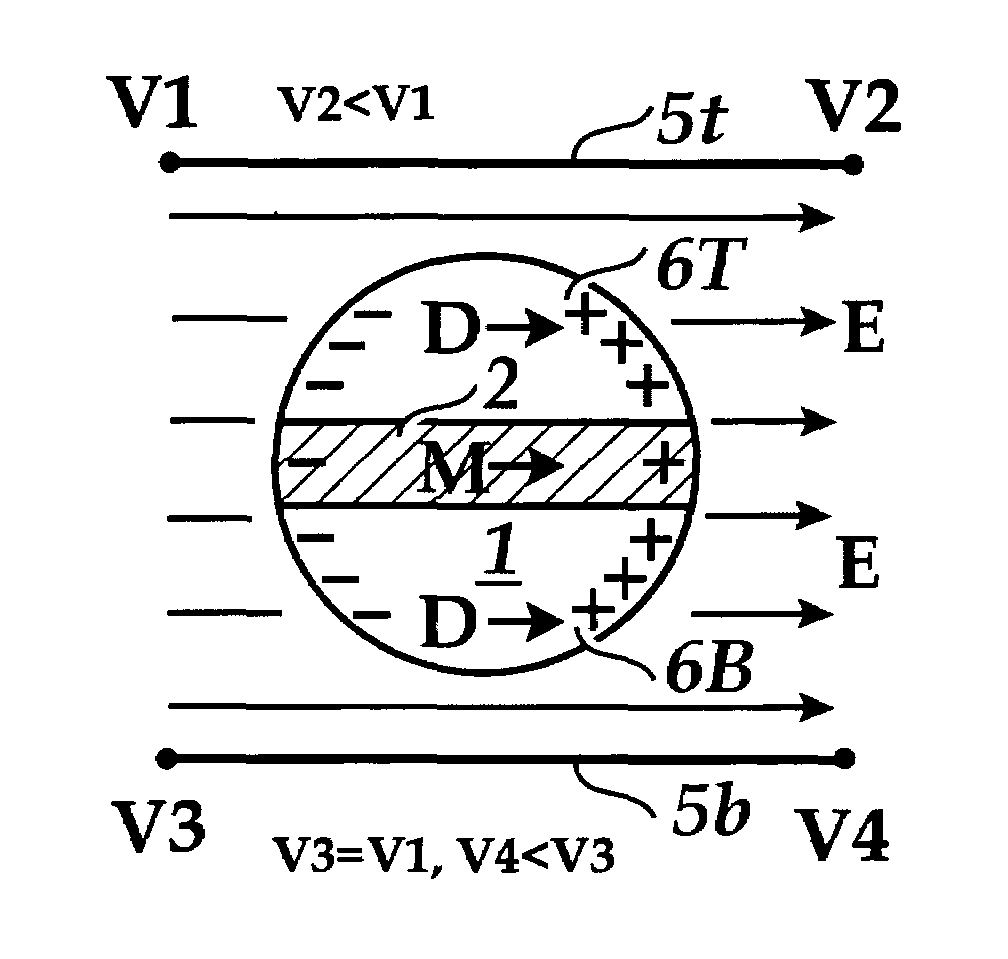
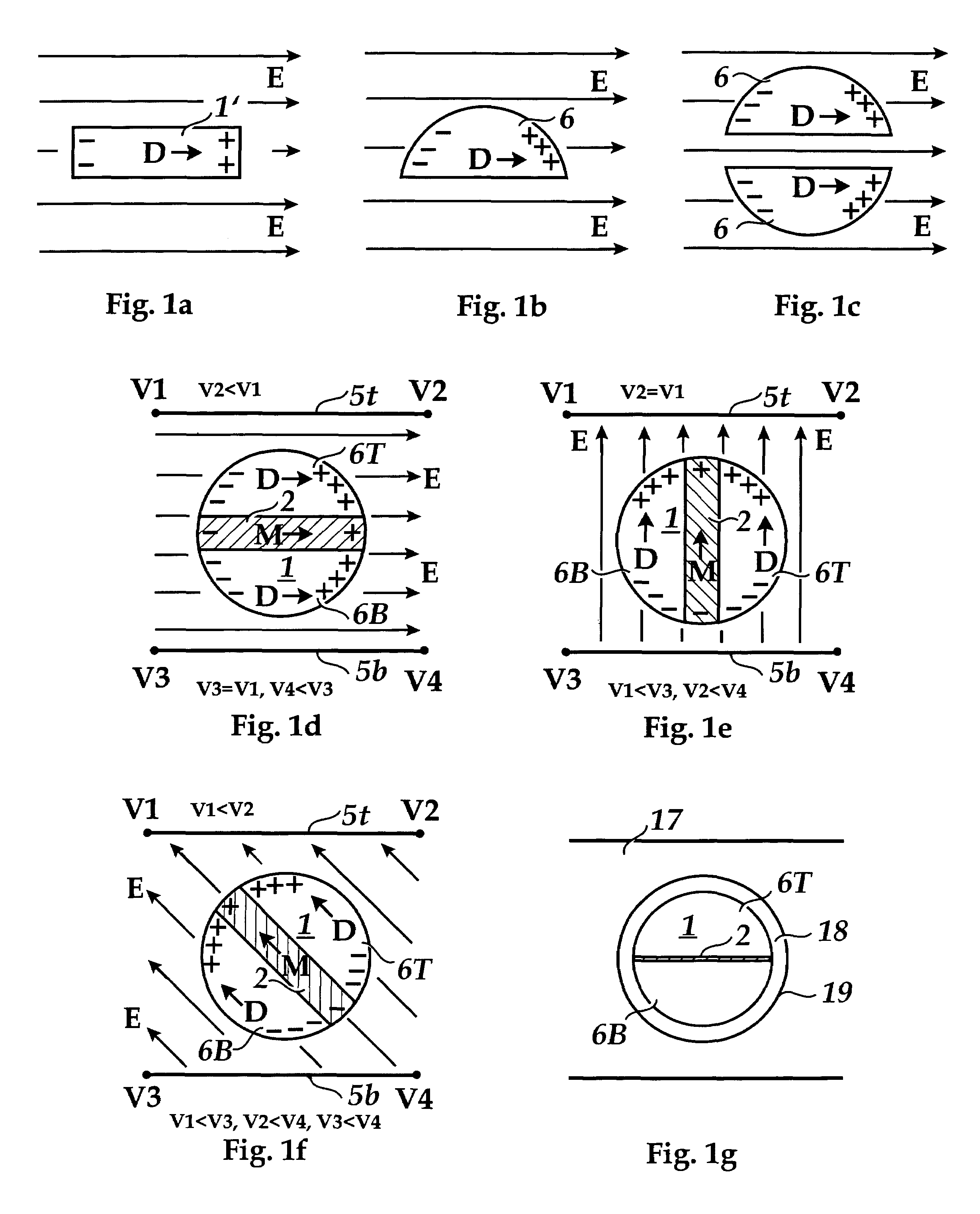
[0061]FIG. 1a is a cross-sectional view of a rotatable dielectric bar 1′ of high aspect ratio, in an applied external electric field E. The electric field E polarizes the bar 1′ with an induced dipole moment D with positive charge + on the right and − charge on the left as shown. D points in the direction of E regardless of the initial orientation of the bar 1′. Because the bar 1′ is constrained to only rotate, this dielectric bar will rotate to align itself in the direction of E, as shown, to lower the potential energy of the system. This is analogous to the rotation of a ferromagnetic bar in an applied magnetic field.

[0062]FIG. 1b is a cross-sectional view of a rotatable dielectric semi-ball 6 of high aspect ratio, in an applied external electric field E. The electric field E polarizes the semi-ball 6 with an induced dipole moment D with positive charge + on the right and − charge on the left as shown. D points in the direction of E regardless of the initial orientation of the sem...


PUM


Abstract

The instant invention is concerned with method and apparatus for induced dipole alignment of solar concentrator micro-mirrors. Novel method and apparatus are taught for coupling to, addressing, and alignment of a micro-optics solar concentrator system for single-axis and two-axis tracking. Mirrored micro-balls are covered with a thin spherical shell of lubricating liquid so that they are free to rotate in an almost frictionless encapsulation in the sheet. Novel method and apparatus are presented for matching the overall ball density with that of the lubricating fluid. Broadly this invention deals with novel concepts used for alignment in the focussing of light wherever mirrors are used for focussing such as for solar propulsion assist, illumination and projection of light, optical switching, etc. A particularly important objective is the focussing of sunlight for solar power conversion and production.

Description

INCORPORATION BY REFERENCE[0001]The following U.S. patents, allowed patent applications, and pending patent applications are fully incorporated herein by reference:[0002]1. U.S. Pat. No. 6,738,176, by Mario Rabinowitz and Mark Davidson, “Dynamic Multi-Wavelength Switching Ensemble” issued on May 18, 2004.[0003]2. U.S. Pat. No. 6,612,705, by Mark Davidson and Mario Rabinowitz, “Mini-Optics Solar Energy Concentrator” issued on Sep. 2, 2003.[0004]3. U.S. Pat. No. 6,698,693 by Mark Davidson and Mario Rabinowitz, “Solar Propulsion Assist” issued on Mar. 2, 2004.[0005]4. U.S. Publication #2003-0193726-A1, by Mark Davidson and Mario Rabinowitz, “Active Reflection, Illumination, and Projection” published on Oct. 16, 2003.[0006]5. U.S. Publication #Not Designated Yet, by Mario Rabinowitz, “Spinning Concentrator Enhanced Solar Energy Alternating Current Producton” is Pending.[0007]6. U.S. Publication #Not Designated Yet, by Mario Rabinowitz, “Manufacturing Transparent Mirrored Mini-Balls for ...

Claims


Application Information

Patent Timeline
Patent Type & Authority Patents(United States)
IPC IPC(8): G02B26/00
CPCF24J2/1057F24J2/16G02B26/026Y02E10/40F24J2002/1076F24S23/77F24S23/82F24S2023/87
Inventor RABINOWITZ, MARIO
Owner RABINOWITZ MARIO
Why Eureka
Try Eureka