Self-referenced locking of optical coherence by single-detector electronic-frequency tagging

a technology of electronic frequency tagging and self-reference, which is applied in the direction of laser optical devices, laser details, antennas, etc., can solve the problems of complex and difficult to implement spatial isolation of phase error signals of previous systems, and achieve the effect of easy scaling

Inactive Publication Date: 2007-03-06
THE GOVERNMENT OF THE UNITED STATES AS REPSESENTED BY THE SEC OF THE AIR FORCE
View PDF8 Cites 65 Cited by
  • Summary
  • Abstract
  • Description
  • Claims
  • Application Information

AI Technical Summary

Benefits of technology

[0006]The present invention is a unique coherent beam combining system for a laser amplifier array. In one embodiment, the output power of the signal from a single master oscillator is split by a 1 by N splitter and directed simultaneously into an array of the N optical modulators where each of the N signals is modulated by a unique electronic frequency. One of these modulated signals is selected as the reference signal. The modulation frequencies must be selected so that beat notes between the reference and other M element optical signals (N−1=M) can be uniquely isolated. The M modulated signals are fed to M phase adjusters and then optically amplified. The reference signal proceeds directly to an amplifier. A small portion of the array output is split off and imaged onto a photodetector. The photodetector output is fed to a signal processor that produces phase error signals that drive the M phase adjustors. The final output is thus a high-powered optically-coherent signal. Thus, a complex and difficult to implement spatial isolation of the phase error signals of previous systems is replaced with an easy to implement electronic isolation of the phase error signals between the reference signal and each of the M modulated optical signals. A single detector is used, and there is no separate reference beam. Furthermore, the method can easily be scaled to large numbers of array elements because the scaling is done in the electronic instead of the spatial domain.

Problems solved by technology

Thus, a complex and difficult to implement spatial isolation of the phase error signals of previous systems is replaced with an easy to implement electronic isolation of the phase error signals between the reference signal and each of the M modulated optical signals.

Method used


Image

  • Self-referenced locking of optical coherence by single-detector electronic-frequency tagging
  • Self-referenced locking of optical coherence by single-detector electronic-frequency tagging
  • Self-referenced locking of optical coherence by single-detector electronic-frequency tagging

Examples


Embodiment Construction

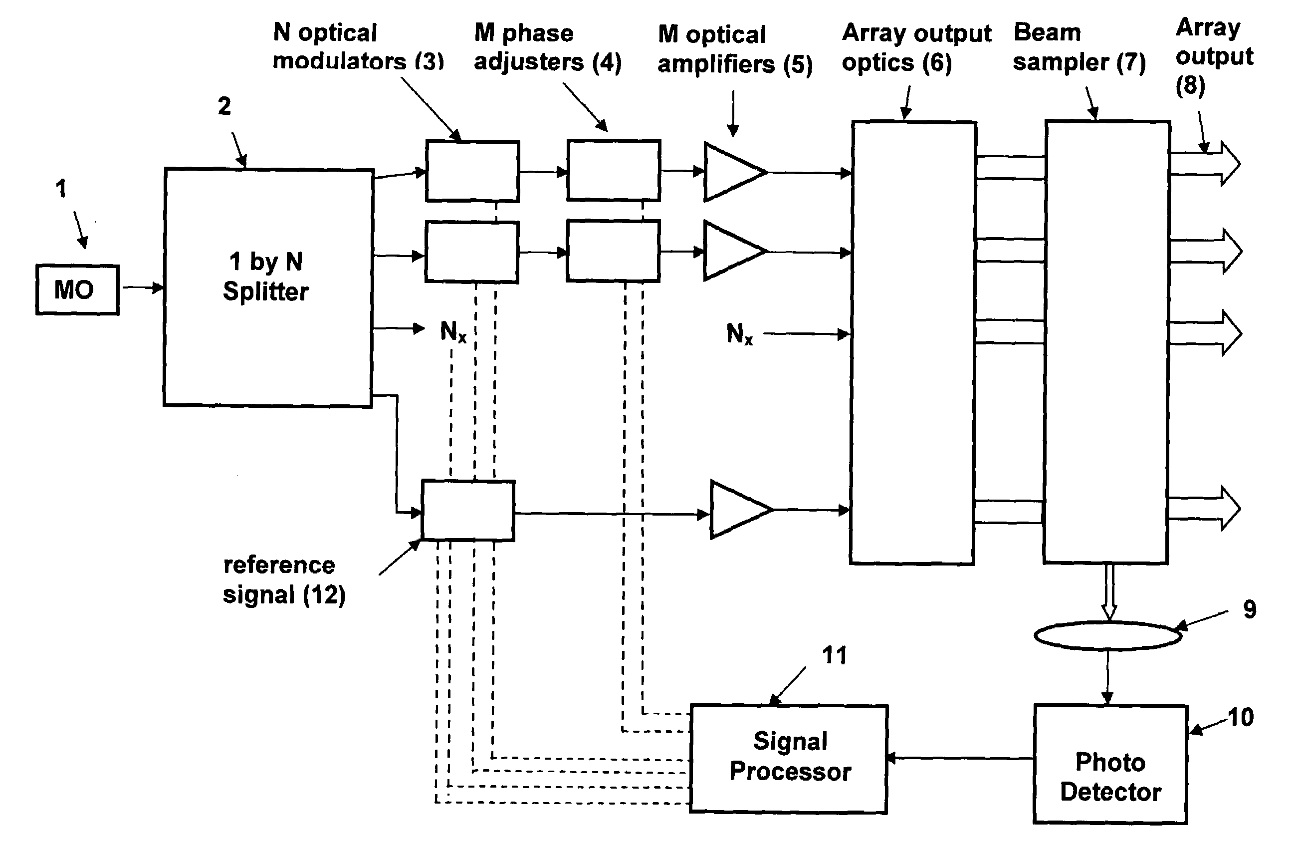
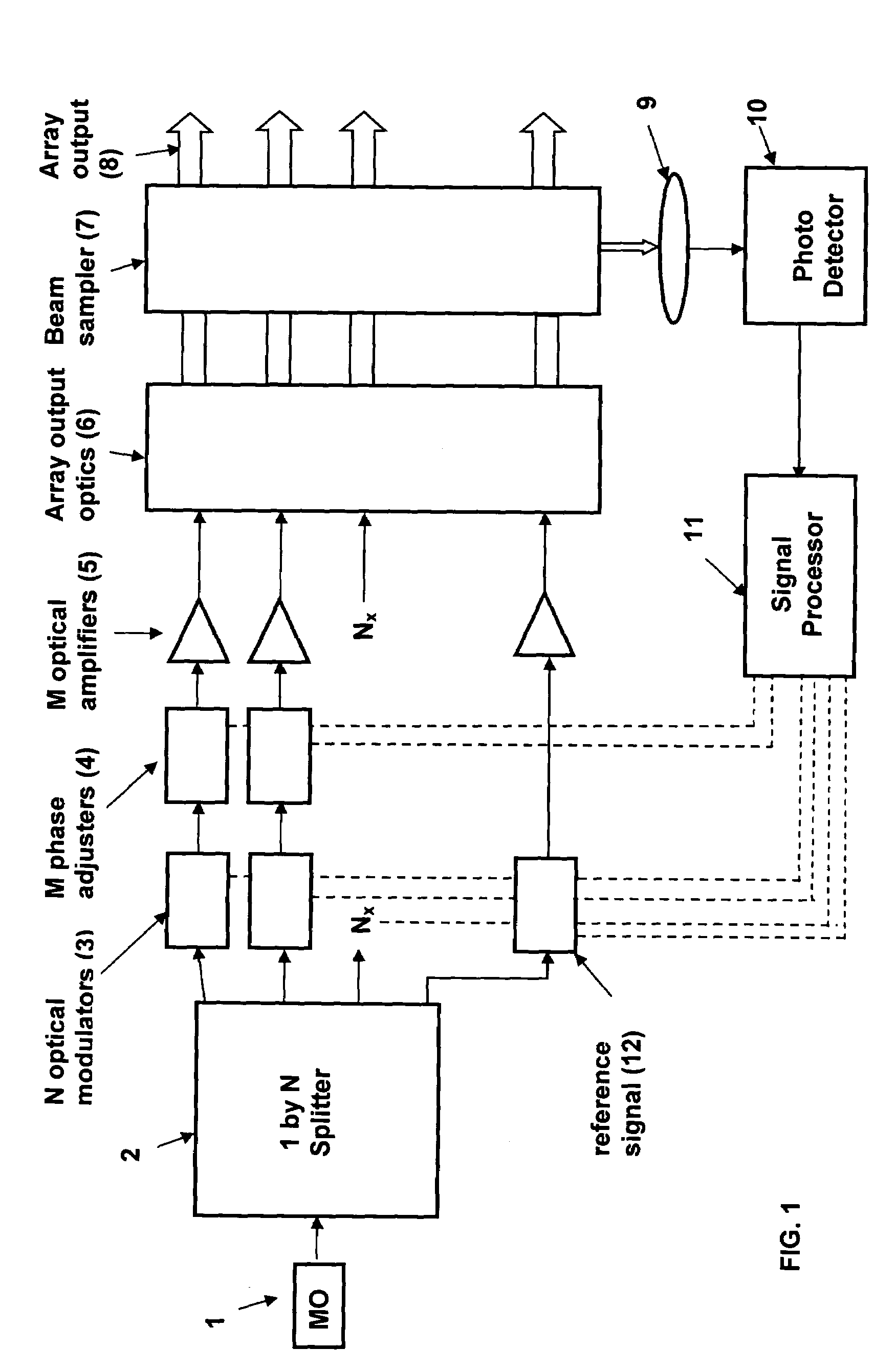
[0012]A novel coherent beam combining system is described that offers not only highly accurate and robust phase locking but is readily scalable to hundreds of elements. Furthermore, this method, called Self-Referenced LOCSET, provides a simple and robust method that needs only a single detector and uses one of the array elements as the reference leg, thus eliminating the need for a separate reference beam. This technology is applicable to general systems of laser amplifiers, i.e. semiconductor, bulk solid state, gas, dye, as well as fiber amplifiers.

[0013]A block diagram of an embodiment of the present invention is shown in FIG. 1. The diagram begins with a master oscillator 1. There may or may not be an optical amplifier incorporated in the master oscillator laser. The output power from the master oscillator divided by a 1×N power splitter 2. Each of the N output signals from the 1×N power splitter 2 is then directed to N optical modulators 3 where each of the N signals is modulate...


PUM


Abstract

A coherent laser beam combining system wherein the output of a single master oscillator is split into a plurality of signals, the signals are electronically modulated at unique frequencies. One signal is designated a reference signal while the remaining signals are passed through phase adjusters. All signals are optically amplified, aligned and passed through a beam splitter to split off a small sample that is imaged onto a photodetector. The photodetector output is fed to a signal processor that produces phase error signals that drive the phase adjusters resulting in a high-powered optically coherent output signal.

Description

STATEMENT OF GOVERNMENT INTEREST[0001]The conditions under which this invention was made are such as to entitle the Government of the United States under paragraph I(a) of Executive Order 10096, as represented by the Secretary of the Air Force, to the entire right, title and interest therein, including foreign rights.BACKGROUND OF THE INVENTION[0002]The present invention relates generally to multiple element optical amplifier arrays used to achieve a high power beam and in particular, to a coherent beam combining system to facilitate such laser amplifier arrays.[0003]The intensity and, hence, the power available from a single-mode optical fiber is limited by either optical surface damage or nonlinear optical effects. These limitations can be overcome by coherent beam-combining of the output power from multiple optical fibers. Fine control of the optical phase is required for any multi-fiber approach. In a master oscillator power amplifier (MOPA) configuration, the optical paths of e...

Claims


Application Information

Patent Timeline
Patent Type & Authority Patents(United States)
IPC IPC(8): H01S4/00H01S3/00
CPCH01S3/2383H01S3/005H01S3/1398H01S3/1301H01S3/0085H01S3/1304H01S3/1307
Inventor SHAY, THOMAS M.
Owner THE GOVERNMENT OF THE UNITED STATES AS REPSESENTED BY THE SEC OF THE AIR FORCE
Why Eureka
Try Eureka