
Methods and apparatus for assembling a gas turbine engine

a gas turbine engine and assembly method technology, applied in the field of gas turbine engines, can solve the problems of relatively complex turbofan-ramjet engines, large displacement, and large displacement, and achieve the effect of increasing the amount of thrus

Active Publication Date: 2007-03-13
GENERAL ELECTRIC CO
View PDF20 Cites 29 Cited by
  • Summary
  • Abstract
  • Description
  • Claims
  • Application Information

AI Technical Summary

Benefits of technology

"The patent describes a gas turbine engine with a flade system that increases the amount of thrust produced by the engine. The engine includes a core engine and a flade duct with a fladed fan and a flade stream augmentor. The method involves channeling airflow through the core engine and flade duct to produce engine thrust, and igniting a portion of the airflow using the flade stream augmentor to increase the amount of thrust produced by the flade system. The technical effect is a more powerful gas turbine engine with improved thrust production."

Problems solved by technology

However such turbofan-ramjet engines are relatively complex and generally include varying disadvantages.
For example, at least one known turbofan-ramjet engine includes a ram burner which is wrapped around a core engine, thus creating an undesirably large diameter engine.
Other known variable cycle engines include variable coannular exhaust nozzles that are relatively complex and difficult to schedule the flow area thereof.
Additionally, these known engines have a high level of base drag associated with the exhaust nozzles.
Moreover, other known variable cycle engines include coannular, separate flow paths including a coannular inlet which creates an undesirably large inlet and which typically requires an inlet diverter valve for selectively channeling inlet air flow.
These known engines may have high levels of spillage around the engine inlet.
Other known engines may include one or more of such undesirable structures, thus resulting in an engine that is relatively complex, heavy, large, and inefficient.

Method used


Image

  • Methods and apparatus for assembling a gas turbine engine
  • Methods and apparatus for assembling a gas turbine engine
  • Methods and apparatus for assembling a gas turbine engine

Examples


Embodiment Construction

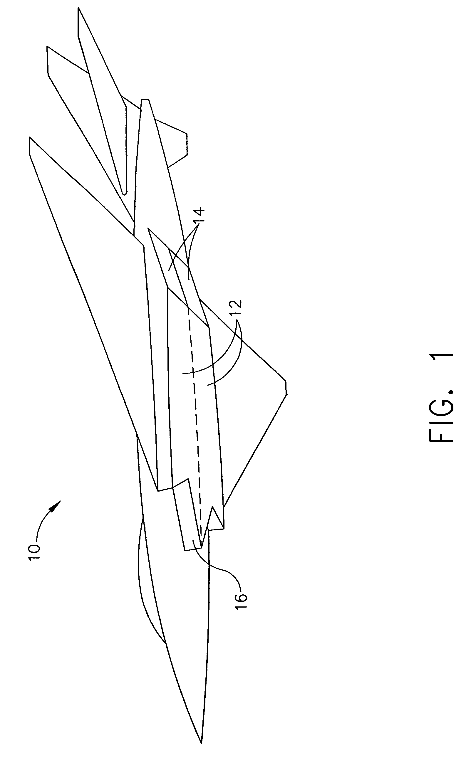
[0010]FIG. 1 is a schematic illustration of a jet aircraft 10 including a plurality of engines 12 and a plurality of nozzle assemblies 14. Aircraft 10 includes an aircraft inlet 16 for channeling airflow to engines 12.

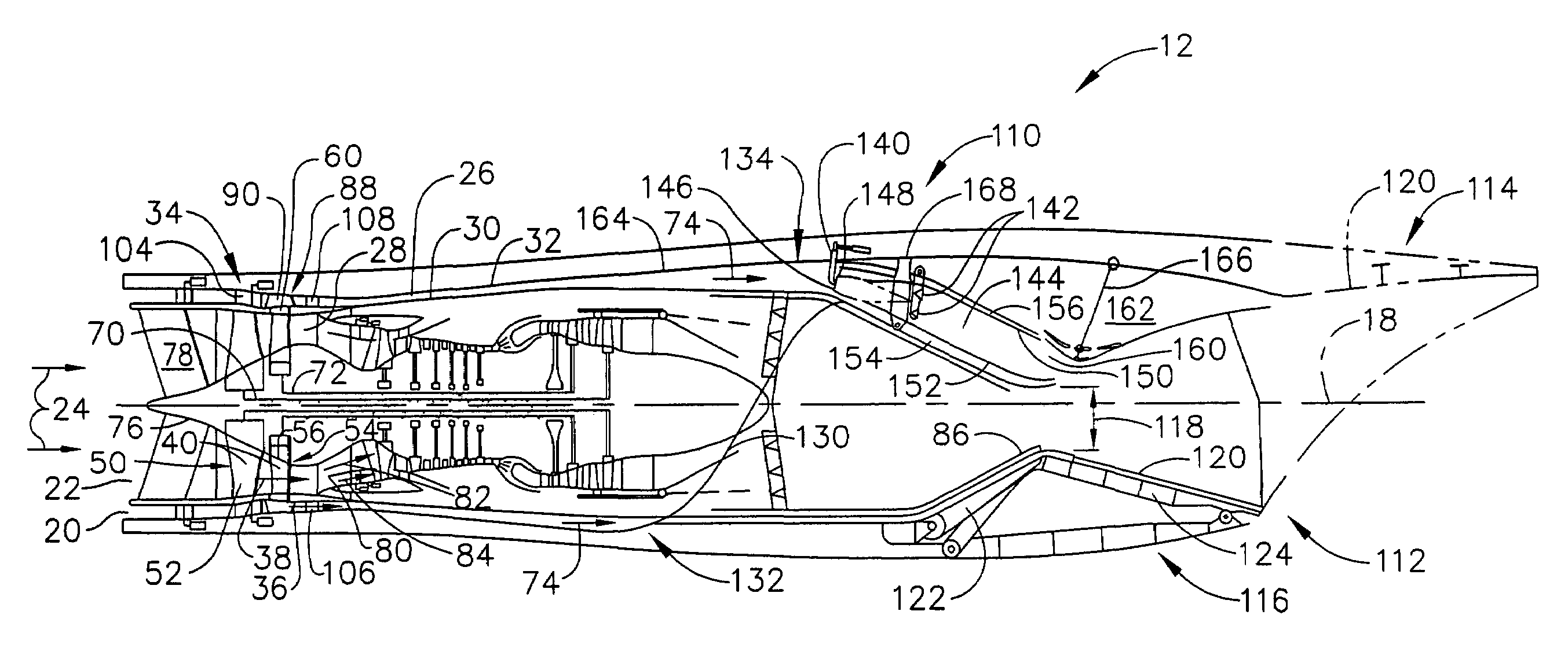
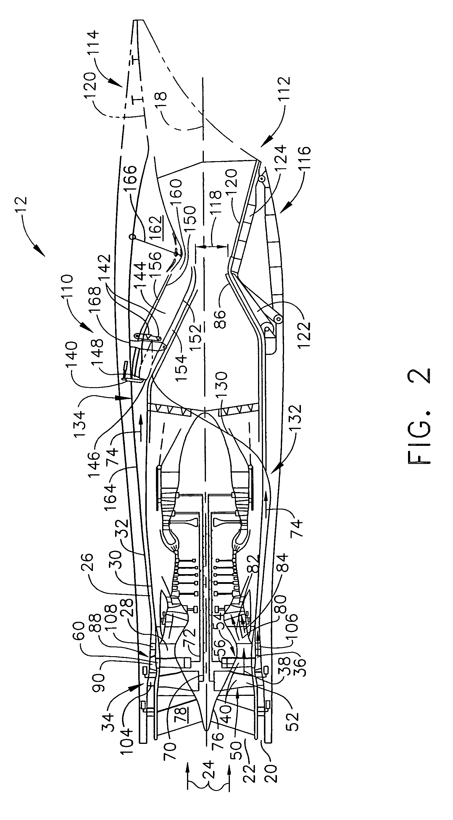
[0011]FIG. 2 is a schematic illustration of an exemplary “fan-on-blade” or fladed engine 12 having an axially oriented engine centerline axis 18. Engine 12 includes a flade inlet 20 and an inner fan inlet 22 through which engine inlet airflow 24 enters during engine operations. In the exemplary embodiment, airflow 24 entering flade inlet 20 flows along a flade duct 26, and airflow 24 entering inner fan inlet 22 flows along an inner fan duct 28. Flade inlet 20 facilitates capturing additional airflow 24 that would otherwise spill around engine 12 leading to spillage drag losses on engine 12. Accordingly, the airflow captured by flade inlet 20 is channeled through engine 12 to improve engine 12 performance by increasing thrust through additional exhaust. Moreover, the ai...


PUM


Abstract

A method for assembling a gas turbine engine includes providing a core engine, and providing a flade system including a flade stream augmentor positioned within a flade duct. The method also includes channeling airflow through the core engine to produce engine thrust, channeling airflow through the flade duct to produce engine thrust, and igniting a portion of the airflow channeled through the flade duct using the flade stream augmentor to increase the amount of thrust produced by the flade system.

Description

BACKGROUND OF THE INVENTION[0001]This invention relates generally to gas turbine engines and more particularly, to methods and apparatus for assembling fladed engines.[0002]Variable cycle engines are conventionally known for powering high performance aircraft from subsonic to supersonic speeds while attempting to obtain countervailing objectives such as high specific thrust and low fuel consumption. In other words, ideal aircraft jet engines attempt to operate through various modes of thrust and speed requirements while minimizing fuel consumption.[0003]Known variable cycle engines are generally operable over a range of operating conditions. In particular, conventional variable cycle combined turbojet or turbofan and ramjet engines generally attempt to provide for a range of operation from low subsonic Mach numbers to high supersonic Mach numbers of about Mach 6. However such turbofan-ramjet engines are relatively complex and generally include varying disadvantages. For example, at ...

Claims


Application Information

Patent Timeline
Patent Type & Authority Patents(United States)
IPC IPC(8): F02K3/02
CPCF02C7/042F02K7/16F02K3/077F02K3/075
Inventor JOHNSON, JAMES EDWARD
Owner GENERAL ELECTRIC CO
Learn More