Counterweight for hydraulic shovel

a hydraulic shovel and counterweight technology, applied in the direction of electric propulsion mounting, jet propulsion mounting, transportation and packaging, etc., can solve the problems of inability to apply the second prior art example to the counterweight of a compact hydraulic shovel, insufficient allowance of inability to maintain the engine and its peripheral equipment. , to achieve the effect of simplifying the structure around the counterweight, and increasing the mass of the counterweigh

Inactive Publication Date: 2007-03-13
KOMATSU LTD
View PDF12 Cites 38 Cited by
  • Summary
  • Abstract
  • Description
  • Claims
  • Application Information

AI Technical Summary

Benefits of technology

[0015]According to the above constitution, it becomes possible to utilize the counterweight, which is conventionally used simply as the heavy load, as the structural component. For example, the left and right supporting column portions of the counterweight also serve as the conventional structural component for supporting the outer casing members and the like, whereby the space for the conventional structural component can be utilized as the space for the counterweight. As a result, the structure around the counterweight can be simplified.
[0016]In the counterweight for the hydraulic shovel, the left and right supporting column portions are constituted as an increase amount of mass of the counterweight. According to this constitution, the mass of the counterweight can be increased by positively utilizing the mass of the left and right supporting column portions as the increase amount of the mass of the counterweight. Accordingly, the mass of the counterweight can be freely distributed among the base portion (main body) and the supporting column portions. For example, the opening area fronting to the engine can be made larger by making the left and right supporting column portions thicker, and the height dimension of the base portion (main body) smaller, and therefore maintainability can be remarkably improved when the engine is maintained from the rear side of the engine over the counterweight.
[0017]In the counterweight for the hydraulic shovel, a floor frame may be supported at the left and right supporting column portions. According to this constitution, the floor frame is firmly supported, and therefore it becomes possible to load the canopy or the cabin directly on the floor frame, for example, and therefore it becomes unnecessary to provide the other rigid frames and the like on the revolving frame. As a result, the degree of freedom of the placement space for the counterweight is increased, and it becomes possible to secure the sufficient mass of the counterweight easily. Accordingly, the upper revolving superstructure has the extremely simple structure, and the assembling man hours and the number of components can be sharply reduced.
[0018]In the counterweight for the hydraulic shovel, at least any one of a canopy, outer casings and engine partition walls may be supported at the left and right supporting column portions. According to this constitution, by attaching the counterweight at the rear end portion of the revolving frame, at least one of the canopy, the outer casings, and the engine partition walls can be supported by the left and right supporting column portions without providing the other frame members vertically. This makes it possible to simplify the mounting structure around the counterweight extremely and reduce the number of components and assembling man hours sharply.
[0019]In the counterweight for the hydraulic shovel, an engine may be placed at a position fronting to between the left and right supporting column portions. According to this constitution, for example, when the engine is placed at the position fronting to between the left and right supporting column portions, in front of the counterweight, it becomes possible to maintain the substantially entire engine from between the left and right supporting column portions over the counterweight. This can remarkably improve the maintainability of the engine.
[0020]In the counterweight for the hydraulic shovel, opening and closing support points of the outer casings may be provided on at least any one of the left and right supporting portions. According to this constitution, the outer casings can be simply attached to the left and right supporting column portions to be openable and closable without using the other frame members and the like. In addition, the opening area is not decreased following the placement of the other frame members and the like, and therefore maintainability of the engine can be remarkably improved.

Problems solved by technology

According to the above-described constitution, there arises the problem that maintainability of the engine and its peripheral equipment is inhibited because a rear surface side of the engine is closed by the counterweight, and various kinds of means are conventionally considered to solve this problem.
However, in the first prior art example, an operation of removing the split counterweight at the region facing the maintenance target part is required when the maintenance operation is performed.
Further, a crane is required for detachment and attachment of the split counterweight, and the construction of connecting portions at the spots where the counterweight is split causes high cost, thereby causing the problem of making it difficult to apply the first prior art example to the counterweight of a compact hydraulic shovel operated in, for example, an urban area.
In the second prior art example, the counterweight needs to be so large as the other parts can make up for large mass loss caused by opening the window portions because three windows as wide as to make the maintenance easy are provided on the counterweight, and therefore there is the problem that it is difficult to apply the second prior art example to the counterweight of a compact hydraulic shovel.
However, in the third prior art example, there arise a few problems as a result of constituting the upper revolving superstructure 50 including the counterweight 52 to be compact though the working machine 5 protrudes forward to be long.
As a first problem, it is difficult to give sufficient allowance to the mass of the counterweight 52 as a result of restraining the height H1 of the counterweight 52.
As a result, there arises the problem that the frequency, at which extra cost, complicated parts management and reduction in function occur, becomes high.
As a result, there arises the problem that the maintainability of the engine 13 is not secured sufficiently.

Method used


Image

  • Counterweight for hydraulic shovel
  • Counterweight for hydraulic shovel
  • Counterweight for hydraulic shovel

Examples


Embodiment Construction

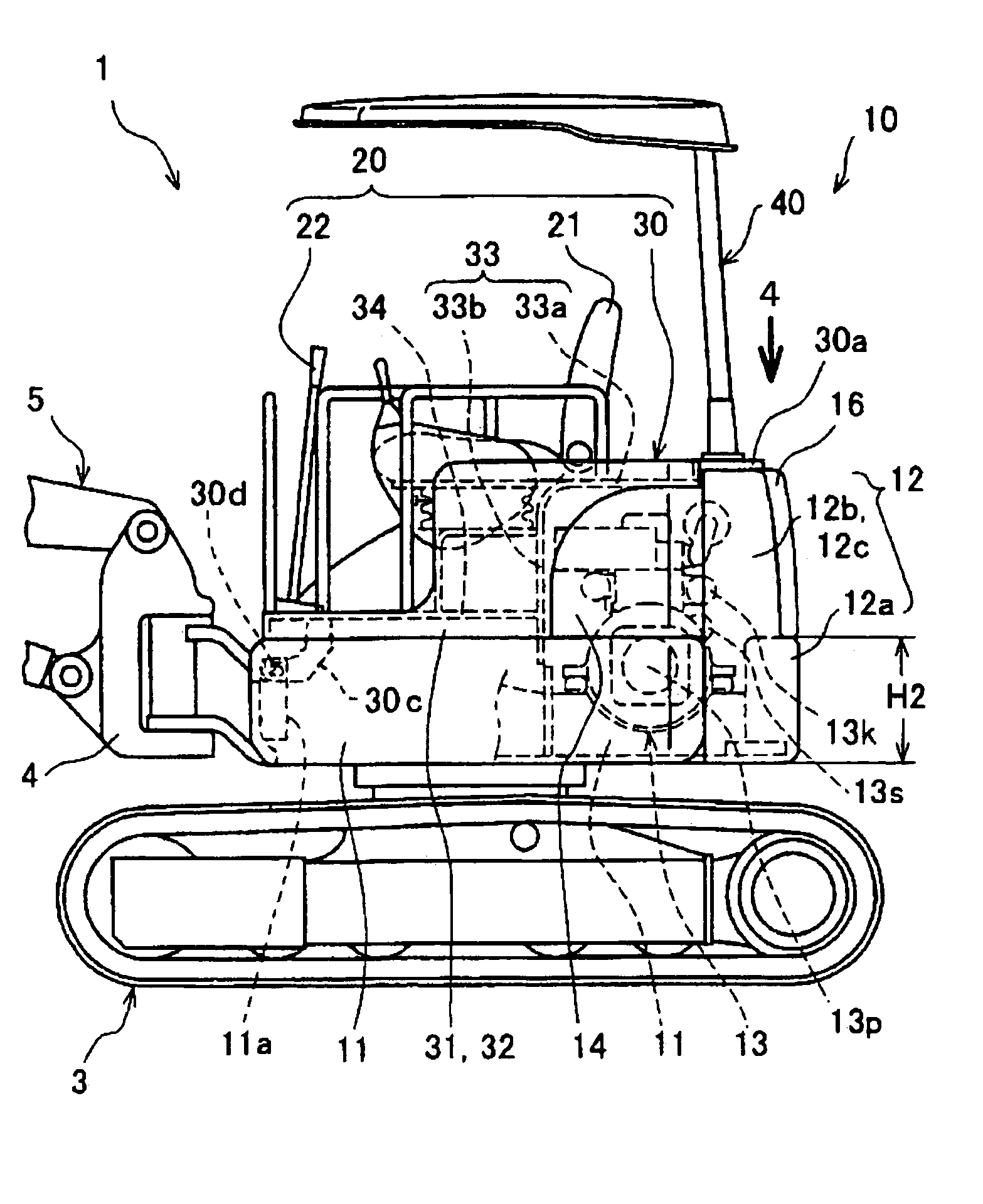
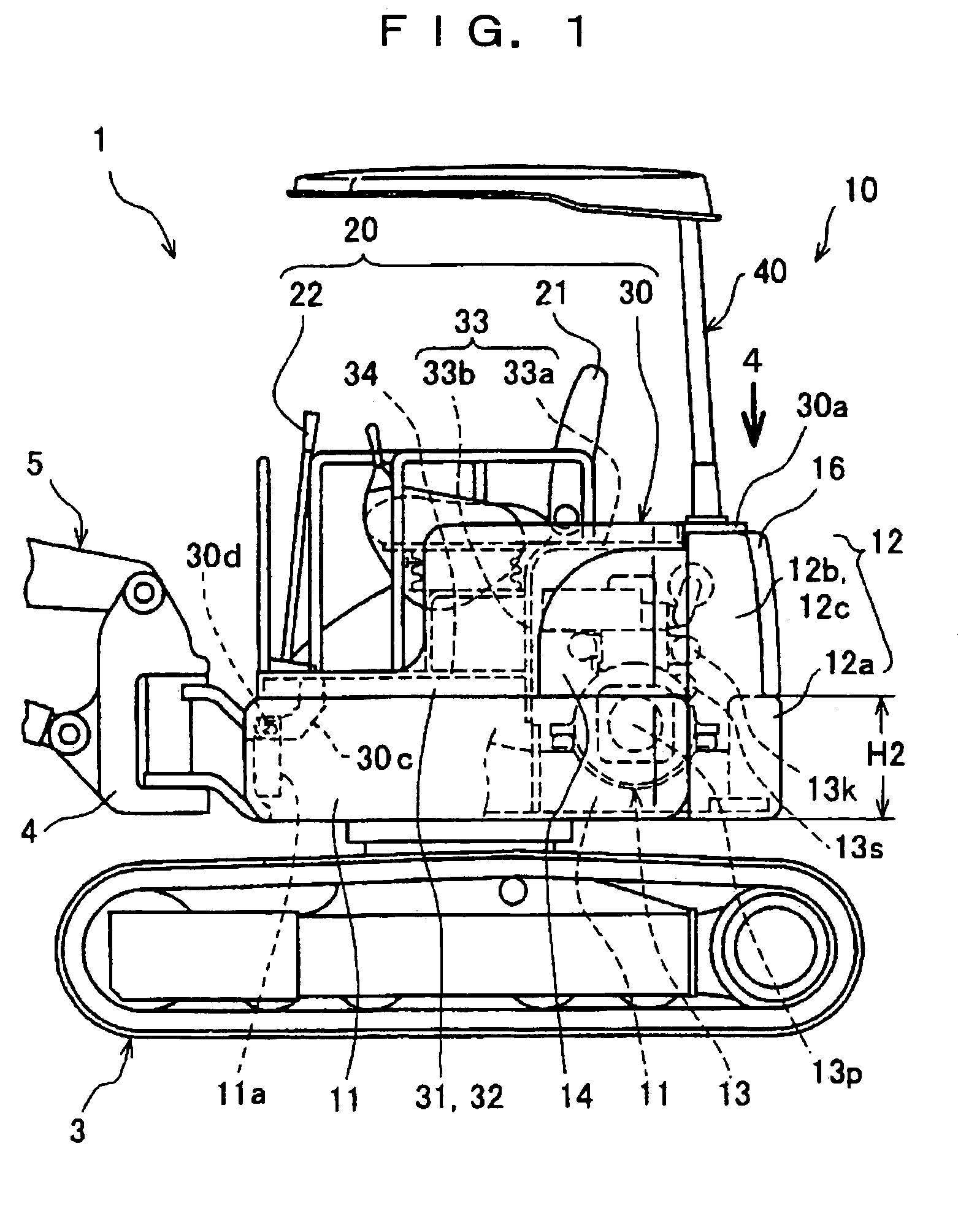
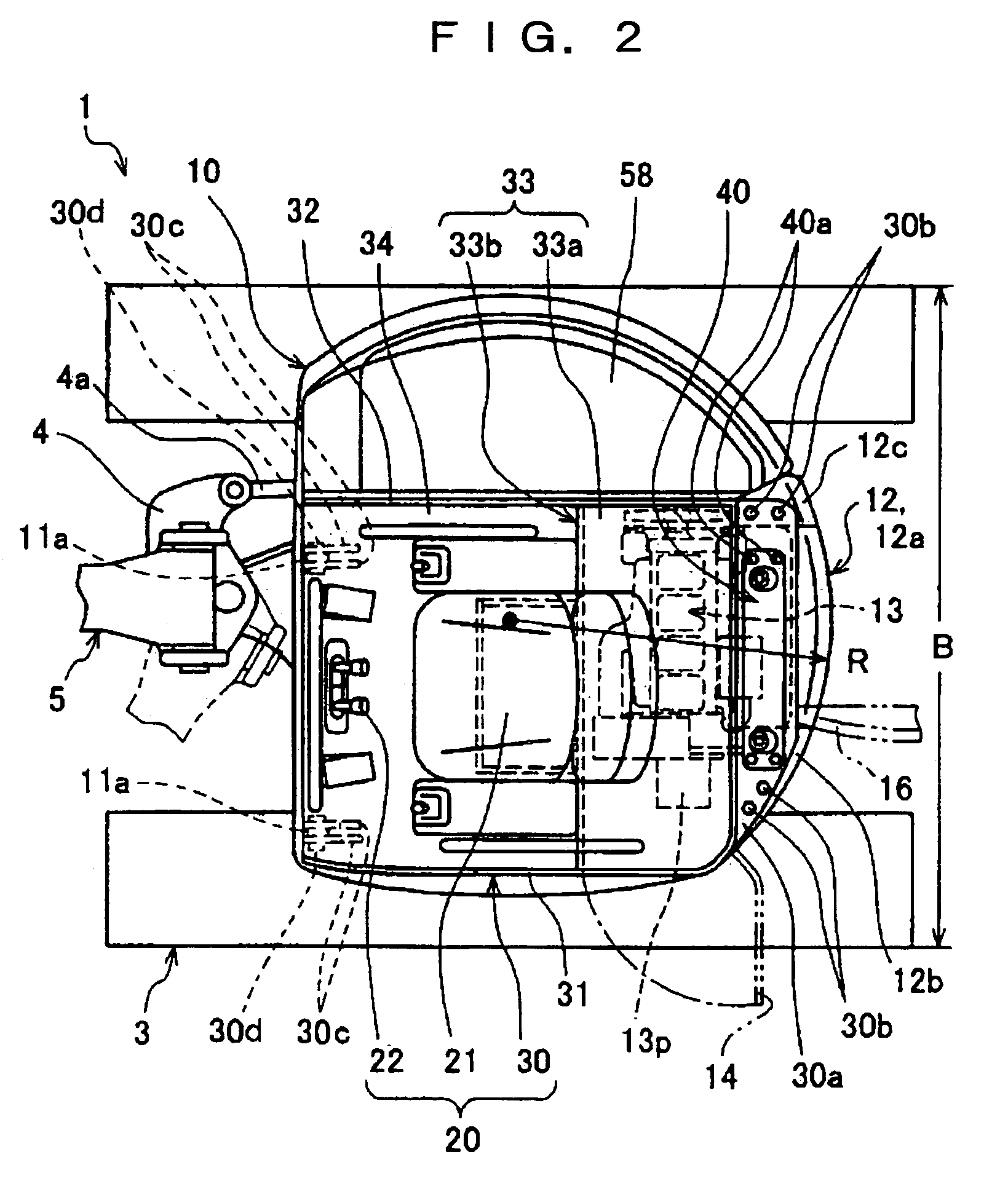
[0028]A preferred embodiment of a counterweight of a hydraulic shovel according to the present invention will be explained in detail with reference to FIG. 1 to FIG. 4 with a compact rear end small revolving hydraulic shovel as an example. First, in FIG. 1 to FIG. 3, a rear end small revolving hydraulic shovel 1 is loaded with an upper revolving superstructure 10 having a constitution, in which a locus of a revolving radius R of a rear end portion is within a lateral external width B of a base carrier 3, on a top portion of the base carrier 3 to be rotatable.

[0029]The upper revolving superstructure 10 has a counterweight 12 fastened to a rear end portion of a revolving frame 11, which is included at a bottom portion, with a predetermined number of bolts 12d. The counterweight 12 is constituted of a central base portion 12a, and supporting column portions 12b and 12c vertically provided at the left and right of the base portion 12a to be protruded upward in a horn shape. By making th...


PUM


Abstract

A counterweight for a hydraulic shovel, which is applicable to a compact to large-sized hydraulic shovels, and is capable of realizing favorable engine maintainability and assurance of sufficient mass, is provided. For this purpose, supporting column portions (12b, 12c) are vertically provided at left and right of a counterweight (12). The left and right supporting column portions are constituted as an increase amount of mass of the counterweight. At least one of a floor frame (30), a canopy (40), outer casings (14, 16) and engine partition walls (33a, 33b) is supported at the left and right supporting column portions. Further, an engine (13) is placed at a position fronting to between the left and right supporting column portions.

Description

TECHNICAL FIELD[0001]The present invention relates to a counterweight for a hydraulic shovel.BACKGROUND ART[0002]In a hydraulic shovel, a working machine is provided at a front part of an upper revolving superstructure, a counterweight is placed at a rear end portion of the upper revolving superstructure and a heavy-mass engine is placed in the vicinity of a front of the counterweight in order to be balanced with the working machine, and a cab seat is placed in front of the engine, in general. In order to simplify the explanation, the term, cab seat, is assumed to be a generic name of an occupied range of an operator, which includes a seat, a foot floor part which is in front of the seat for the operator to place his or her feet on, and an operating device having an operating lever and the like. When only the seat is to be indicated, it is distinguished from the cab seat by calling it as an operator seat. The same shall apply hereinafter.[0003]According to the above-described consti...

Claims


Application Information

Patent Timeline
Patent Type & Authority Patents(United States)
IPC IPC(8): B60S9/22E02F9/08E02F9/18
CPCE02F9/0833E02F9/18E02F9/0866
Inventor SUGIYAMA, KIYOSHIOHMURA, JUNICHIANDOU, TAKENOBU
Owner KOMATSU LTD
Why Eureka
Try Eureka