Phosphor, light emitting device using phosphor, and display and lighting system using light emitting device

a light emitting device and light emitting device technology, applied in the direction of luminescent compositions, discharge tubes/lamp details, discharge tubes luminescent compositions, etc., can solve the problems of low color rendering property of light emitting devices, phosphor is not necessarily easy to produce, and phosphor tends to be deteriorated in brightness

Inactive Publication Date: 2007-03-13
MITSUBISHI CHEM CORP
View PDF6 Cites 82 Cited by
  • Summary
  • Abstract
  • Description
  • Claims
  • Application Information

AI Technical Summary

Problems solved by technology

The phosphor is not necessarily easily produced owing to its high calcination temperature, etc.
In addition, the phosphor tends to be deteriorated in brightness with the increase in temperature upon use.
Therefore, when the phosphor is applied to displays or lighting systems, the brightness thereof tends to be lowered with the temperature rise of these apparatuses, resulting in problems such as low color rendering property of the light emitting device.
However, the use of such a light emitting substance is industrially disadvantageous since a Ge compound as a raw material thereof is very expensive.

Method used


Image

  • Phosphor, light emitting device using phosphor, and display and lighting system using light emitting device
  • Phosphor, light emitting device using phosphor, and display and lighting system using light emitting device
  • Phosphor, light emitting device using phosphor, and display and lighting system using light emitting device

Examples


example 1

[0055]0.0297 mol of CaCO3 as a M1-source compound, 0.01 mol of Sc2O3 as a M2-source compound, 0.03 mol of SiO2 as a M3-source compound and 0.0003 mol of Ce(OCOCH3)3 as a luminescent center ion element-source compound were pulverized and mixed together with pure water in a wet ball mill including an alumina container and beads, dried and then passed through a nylon mesh. The resultant pulverized mixture was heat-calcined in an alumina crucible under atmospheric air at 1,400° C. for 2 hours, and successively subjected to water-washing, drying and classification, thereby producing a phosphor.

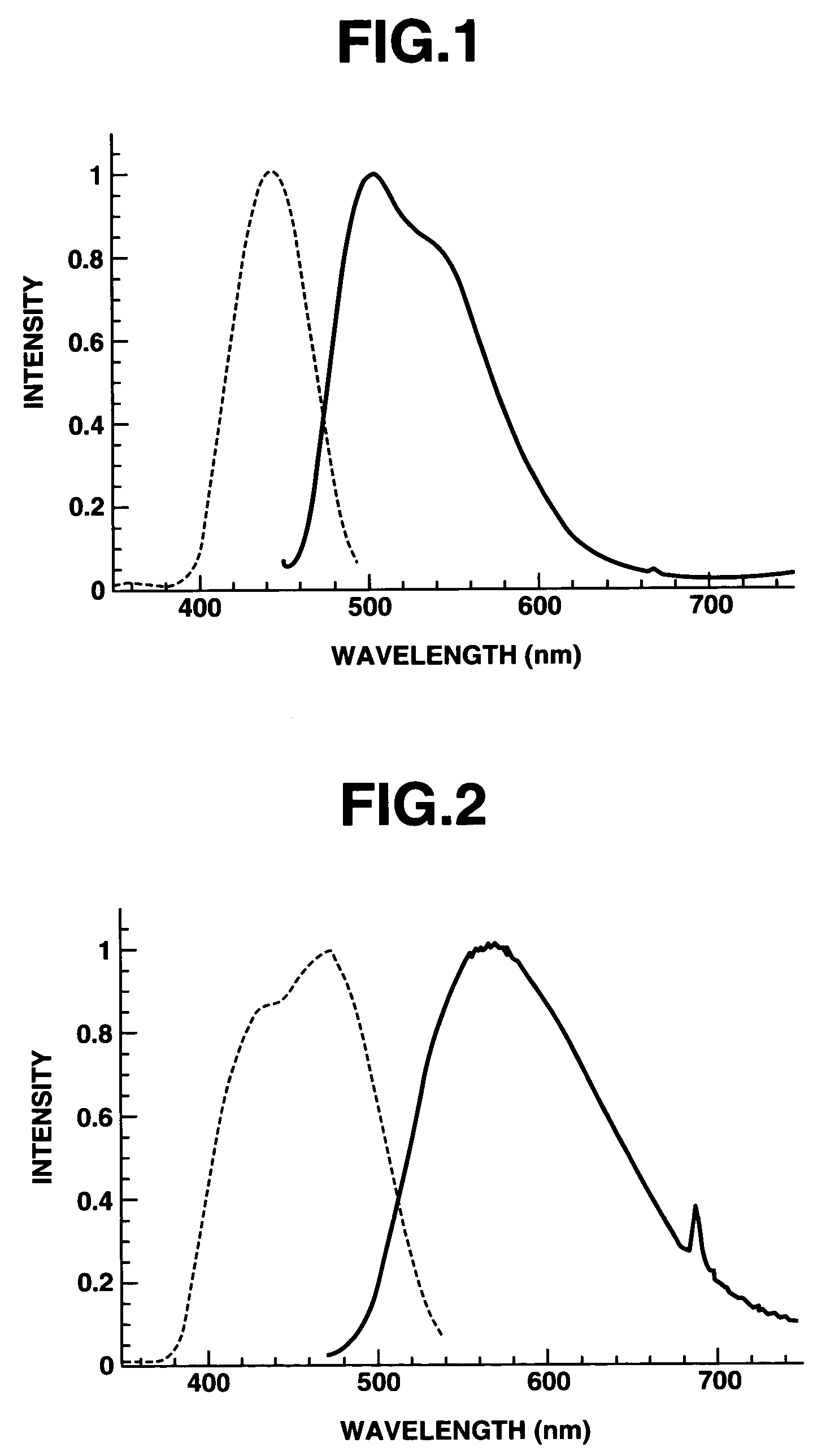
[0056]As a result of analyzing the thus obtained phosphor by powder X-ray diffraction method, it was confirmed that the phosphor contained a host material composed of a compound of a garnet crystal structure having a composition as shown in Table 1, and trivalent Ce as a luminescent center ion incorporated in the host material. Further, the phosphor was subjected to measurements of emission spectru...

example 2

[0057]The same procedure as defined in Example 1 was conducted except that 0.0147 mol of CaCO3 and 0.015 mol (as Mg) of Mg(OH)2.3MgCO30.3H2O were used as a M1-source compound, and 0.0075 mol of Sc2O3 and 0.0025 mol of Y2O3 were used as a M2-source compound, thereby producing a phosphor. As a result of analyzing the thus obtained phosphor by powder X-ray diffraction method, it was confirmed that the phosphor contained a host material composed of a compound of a garnet crystal structure having a composition as shown in Table 1, and trivalent Ce incorporated as a luminescent center ion in the host material. Further, the phosphor was subjected to measurements of emission spectrum and excitation spectrum thereof. The results are shown in FIG. 2. From the thus measured emission spectrum, the color coordinates x and y were calculated by the same method as in Example 1. As a result, it was confirmed that x was 0.43 (x=0.43), y was 0.53 (y=0.53), and a sum of x and y was 0.96 ((x+y)=0.96). F...

example 3

[0058]The same procedure as defined in Example 1 was conducted except that the heat-treating temperature was changed to 1,200° C., thereby producing a phosphor. As a result of analyzing the thus obtained phosphor by powder X-ray diffraction method, it was confirmed that the phosphor contained a host material composed of a compound of a garnet crystal structure having a composition as shown in Table 1, and trivalent Ce incorporated as a luminescent center ion in the host material. From the measured emission spectrum of the phosphor, the color coordinates x and y were calculated by the same method as in Example 1. As a result, it was confirmed that x was 0.28 (x=0.28), y was 0.54 (y=0.54), and a sum of x and y was 0.82 ((x+y)=0.82). Further, the phosphor was irradiated with a blue light by the same method as in Example 1, while controlling an irradiation intensity thereof. As a result, the phosphor absorbed the blue light and emitted a yellowish green color light, and further the emit...


PUM

PropertyMeasurementUnit
color rendering index R5aaaaaaaaaa
color rendering index Raaaaaaaaaaa

Abstract

A phosphor (A) comprising a host material composed of a compound having a garnet crystal structure represented by the general formula (I):M1aM2bM3cOd  (I)(wherein M1 is a divalent metal element, M2 is a trivalent metal element, M3 is a tetravalent metal element containing at least Si, a is the number of 2.7 to 3.3, b is the number of 1.8 to 2.2, c is the number of 2.7 to 3.3, and d is the number of 11.0 to 13.0), and a luminescent center ion incorporated in the host material; a light emitting device (B) comprising the phosphor as a wavelength conversion material and a semiconductor light emitting element capable of emitting a light in the range of from ultraviolet light to visible light; and a display (C) and a lighting system (D) using the light emitting device (B) as a light source. The above phosphor can be readily produced, and can provide a light emitting device having a high color rendering property.

Description

TECHNICAL FIELD[0001]The present invention relates to a phosphor, a light emitting device using the phosphor, and a display and a lighting system using the light emitting device. More particularly, the present invention relates to a phosphor including a host material compound and a luminescent center ion incorporated therein, which is useful as a wavelength conversion material capable of absorbing a light in the range of from ultraviolet light to visible light and emitting a visible light having a longer wavelength than that of the absorbed light, and can provide a light emitting device having a high color rendering property when used in combination with a semiconductor light emitting element such as light emitting diodes (LED) and laser diodes (LD), a light emitting device using such a phosphor, and a display and a lighting system using such a light emitting device as a light source thereof.BACKGROUND ARTS[0002]Hitherto, white light emitting devices constituted by the combination o...

Claims


Application Information

Patent Timeline
Patent Type & Authority Patents(United States)
IPC IPC(8): C09K11/08C09K11/79C09K11/59C09K11/66C09K11/77H01J1/62H01J63/04H01L33/50
CPCC09K11/0883C09K11/665C09K11/7721C09K11/7728C09K11/7734C09K11/7774C09K11/7789C09K11/7731H01L33/502H01L2924/181H01L2224/48091H01L2224/48247H01L2224/48257H01L2224/49107H01L2224/8592H01L2224/45144C09K11/77742H01L2924/00012H01L2924/00014H01L2924/00
Inventor SHIMOMURA, YASUOKIJIMA, NAOTO
Owner MITSUBISHI CHEM CORP
Why Eureka
Try Eureka