Active feedback-controlled bass coloration abatement

a feedback control and bass technology, applied in the field of active feedback control bass coloration abatement, can solve the problems of muddy or unintelligible sound, too little can make it sound dry or dead, and reinforcement and lingering of certain tones in music, so as to reduce the low-frequency coloration of sound

Inactive Publication Date: 2007-03-13
DESIGN IMAGING & CONTROL
View PDF19 Cites 17 Cited by
  • Summary
  • Abstract
  • Description
  • Claims
  • Application Information

AI Technical Summary

Benefits of technology

[0017]Accordingly, it is an object of the present invention to provide a system and method that effectively reduces the low-frequency coloration of sound within a listening room, particularly a listening room where the coloration generated within the listening room is dominated by at least one mode of low-frequency coloration. It is a further object of the present invention to provide a system for actively treating noise within fluid-carrying ducts. Other objects of the present invention will be apparent in light of the description of the invention embodied herein.

Problems solved by technology

While too much reverberation of sound within an enclosure can make music sound muddy or unintelligible, too little can make it sound dry or dead.
However, as a result of their size and geometry, certain rooms can accommodate excessive reverberation of sound at particular frequencies, resulting in the reinforcement and lingering of certain tones in music, after they should normally have ceased.
Sounds reflecting from surface to surface can interfere at certain frequencies, resulting in acoustic resonance; the intensification of sound.
In particular, listening rooms with small dimensions exhibit severe coloration in the bass or upper low-frequency region.

Method used


Image

  • Active feedback-controlled bass coloration abatement
  • Active feedback-controlled bass coloration abatement
  • Active feedback-controlled bass coloration abatement

Examples


Embodiment Construction

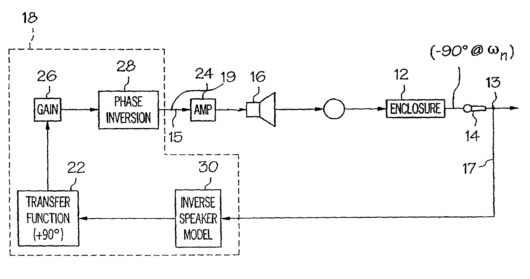
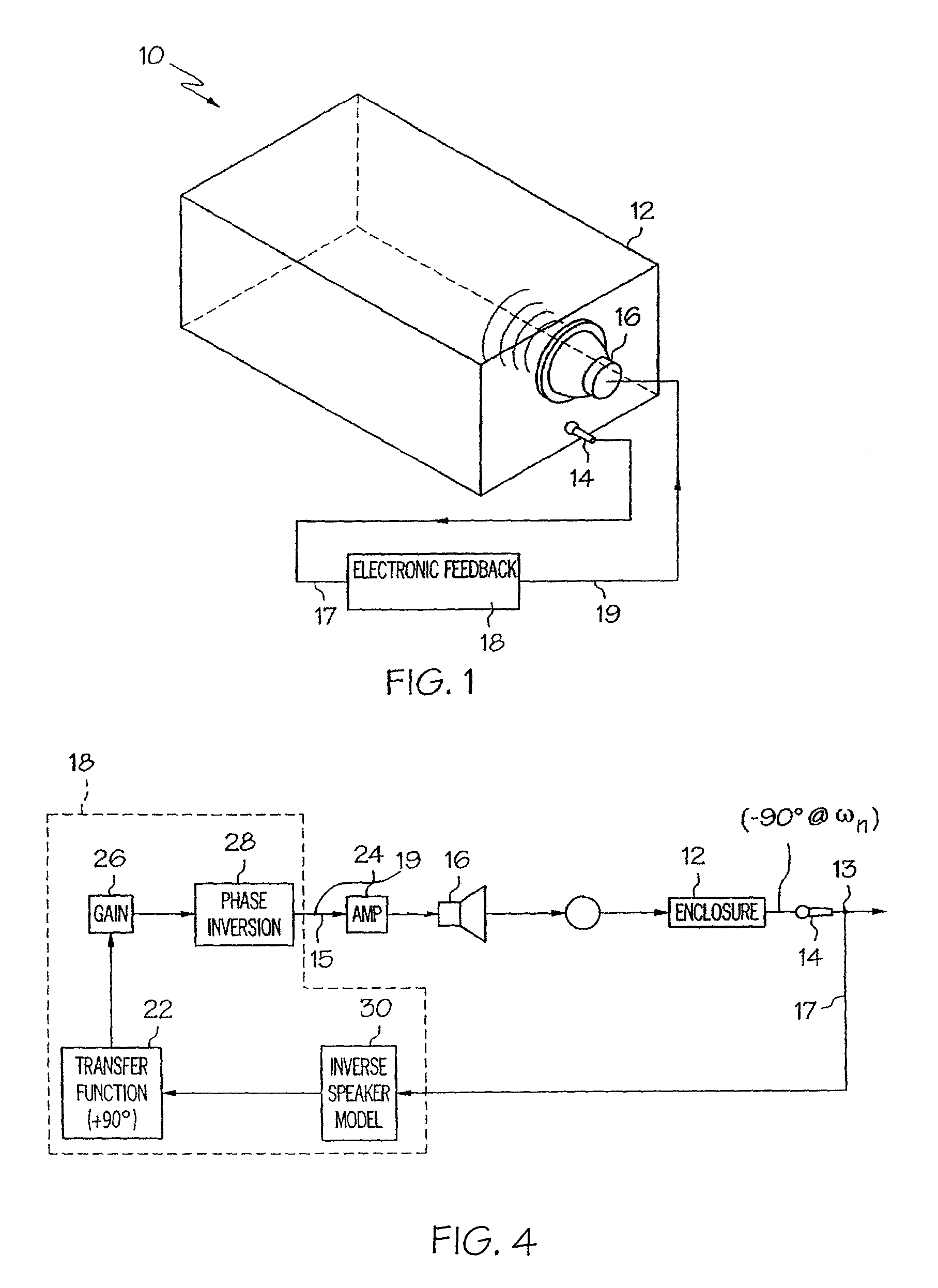
[0031]Referring initially to FIG. 1, a system for actively damping the low-frequency coloration of sound 10 according to the present invention is illustrated in general schematic form. The system 10 employs a feedback control scheme for reducing the boominess of sound at frequencies corresponding to offending (coloring) standing waves within a listening room. The system comprises a listening room 12, an acoustic wave sensor 14, an acoustic wave actuator 16, and an electronic feedback controller 18. As will be appreciated by those skilled in the art of acoustics, the listening room 12 defines at least one mode of low-frequency coloration. For the purposes of defining and describing the present invention, it should be understood that a listening room typically comprises any completely bounded three dimensional space, but may also comprise a three dimensional space including some relatively insubstantial unbounded portions, which is used for listening to music and / or other sounds, or f...


PUM


Abstract

A system for actively damping the low-frequency coloration of sound in a listening room is provided comprising an acoustic wave sensor, an acoustic wave actuator, and an electronic feedback controller. The listening room defines at least one mode of low-frequency coloration. The acoustic wave actuator is substantially collocated with the acoustic wave sensor within the listening room. The electronic feedback controller is operative to generate a signal at its output by applying a feedback controller transfer function. The feedback controller transfer function comprises a second order differential equation including a first variable representing a predetermined damping ratio and a second variable representing a tuned natural frequency and creates a 90 degree phase lead substantially at the resonant frequencies of at least one mode of low-frequency coloration. The feedback controller output signal represents a rate of change of volume velocity to be produced by the acoustic wave actuator. Further provided are methods for actively damping the low-frequency coloration of sound within a listening room and systems for actively treating noise within a fluid-carrying duct, including those which employ active low- and high-pass acoustic filters.

Description

CROSS-REFERENCE TO RELATED APPLICATIONS[0001]This application is a continuation-in-part of U.S. patent application Ser. No. 09 / 991,895, filed Nov. 6, 2001 now abandoned and claiming priority to U.S. Provisional Application Ser. No. 60 / 246,253, filed Nov. 6, 2000.BACKGROUND OF THE INVENTION[0002]The present invention relates in general to systems and methods for influencing sound within an enclosure and, more particularly, to a system and method that reduces the bass coloration of sound within a listening room by actively damping low-frequency boom noise, as well as other systems for actively damping noise within fluid-carrying ducts.[0003]The experience of hearing sound in a specially designed listening environment, such as a listening room, concert hall, recording or sound studio, or other like enclosure, is affected almost as much by the dimensions of the enclosure itself as it is by the quality of the source. A properly designed listening environment enables the listener to clear...

Claims


Application Information

Patent Timeline
Patent Type & Authority Patents(United States)
IPC IPC(8): H03B29/00
CPCH03G3/32H04R3/002H03G5/18
Inventor KASHANI, AHMAD REZA
Owner DESIGN IMAGING & CONTROL
Why Eureka
Try Eureka