Method and apparatus for automated image analysis of biological specimens

Inactive Publication Date: 2007-03-13
CARL ZEISS MICROIMAGING AIS
View PDF176 Cites 94 Cited by
  • Summary
  • Abstract
  • Description
  • Claims
  • Application Information

AI Technical Summary

Benefits of technology

[0005]A problem with the foregoing automated system is the continued need for operator input to initially locate cell objects for analysis. Such continued dependence on manual input can lead to errors including cells or objects of interest being missed. Such errors can be critical especially in assays for so-called rare events, e.g., finding one tumor cell in a cell population of one million normal cells. Additionally, manual methods can be extremely time consuming and can require a high degree of training to identify and/or quantify cells. This is not only true for tumor cell identification and detection, but also for o

Problems solved by technology

A problem with the foregoing automated system is the continued need for operator input to initially locate cell objects for analysis.
Such continued dependence on manual input can lead to errors including cells or objects of interest being missed.
Additionally, manual meth

Method used


Image

  • Method and apparatus for automated image analysis of biological specimens
  • Method and apparatus for automated image analysis of biological specimens
  • Method and apparatus for automated image analysis of biological specimens

Examples


Example

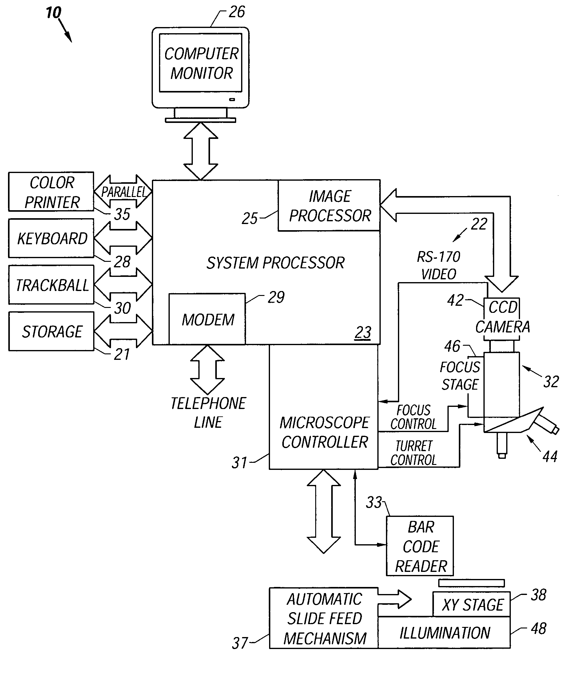
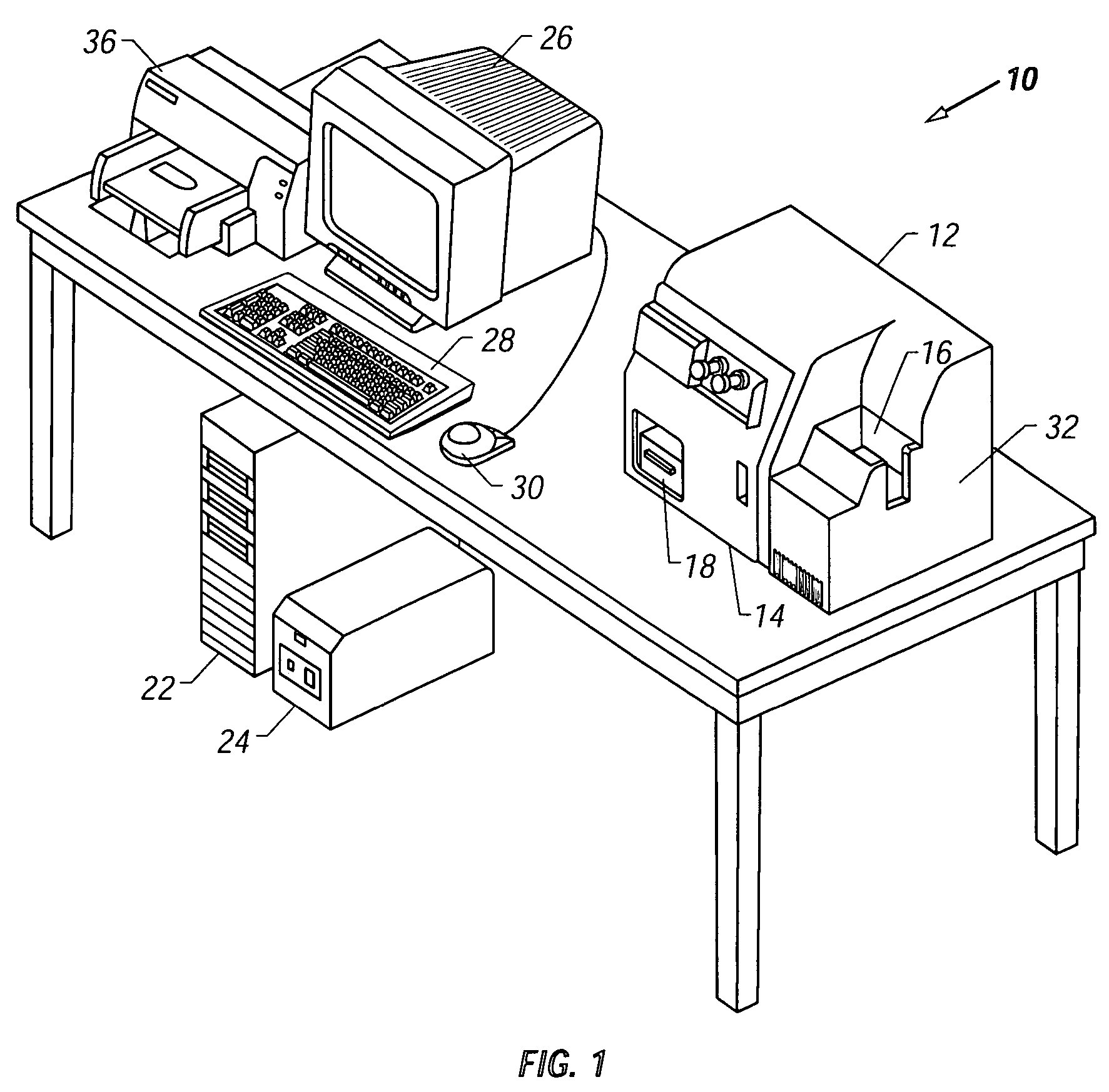
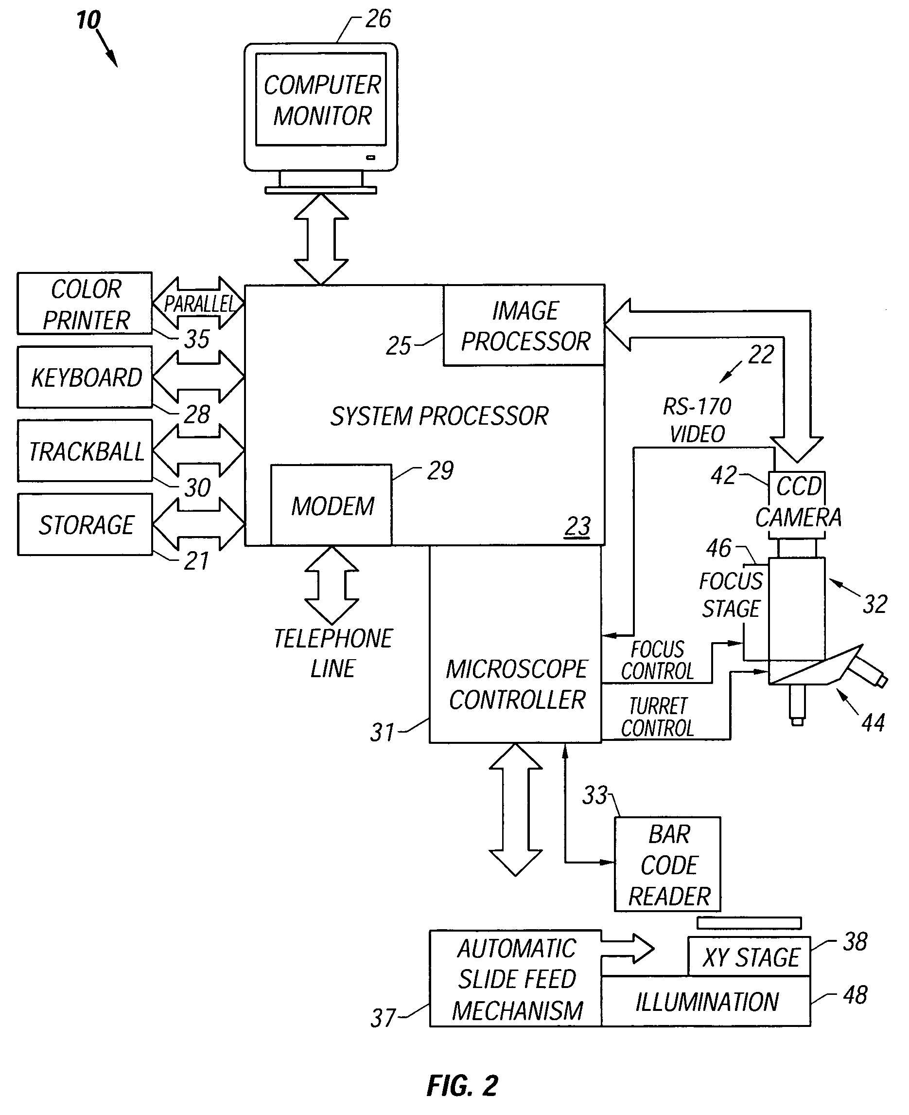
[0045]Referring now to the figures, an apparatus for automated cell analysis of biological specimens is generally indicated by reference numeral 10 as shown in perspective view in FIG. 1 and in block diagram form in FIG. 2. The apparatus 10 comprises a microscope subsystem 32 housed in a housing 12. The housing 12 includes a slide carrier input hopper 16 and a slide carrier output hopper 18. A door 14 in the housing 12 secures the microscope subsystem from the external environment. A computer subsystem comprises a computer 22 having at least one system processor 23, and a communications modem 29. The computer subsystem further includes a computer monitor 26 and other external peripherals including storage device 21, a pointing device, such as a track ball device 30, a user input device, such as a touch screen, keyboard, or voice recognition unit 28 and color printer 35. An external power supply 24 is also shown for power outage protection. The apparatus 10 further includes an optica...


PUM


Abstract

A method and apparatus for automated cell analysis of biological specimens automatically scans at a low magnification to acquire images (288) which are analyzed to determine candidate cell objects of interest. The low magnification images are converted from a first color space to a second color space (290). The color space converted image is then low pass filtered (292) and compared to a threshold (294) to remove artifacts and background objects from the candidate object of interest pixels of the color converted image. The candidate object of interest pixels are morphologically processed (296) to group candidate object of interest pixels together into groups which are compared to blob parameters (298) to identify candidate objects of interest which correspond to cells or other structures relevant to medical diagnosis of the biological specimen. The location coordinates of the objects of interest are stored and additional images of the candidate cell objects are acquired at high magnification. The high magnification images are analyzed in the same manner as the low magnification images to confirm the candidate objects of interest which are objects of interest. A high magnification image of each confirmed object of interest is stored for later review and evaluation by a pathologist.

Description

CROSS REFERENCE TO RELATED APPLICATIONS[0001]This application is a continuation of U.S. patent application Ser. No. 09 / 495,461, filed Feb. 1, 2000 (now issued as U.S. Pat. No. 6,718,053), which is a continuation-in-part of U.S. patent application Ser. No. 09 / 344,308, filed Jun. 24, 1999 (now issued as U.S. Pat. No. 6,418,236), which claims priority to Provisional Application Ser. No. 60 / 129,384, filed Apr. 13, 1999, and is a continuation-in-part of U.S. patent application Ser. No. 08 / 827,268, filed Mar. 28, 1997 (now issued as U.S. Pat. No. 6,151,405), which is a continuation-in-part of U.S. patent application Ser. No. 08 / 758,436 filed on Nov. 27, 1996 (now issued as U.S. Pat. No. 6,215,892).TECHNICAL FIELD[0002]The invention relates generally to light microscopy and, more particularly, to automated light microscopic methods and an apparatus for detection of objects in a sample.BACKGROUND OF THE INVENTION[0003]In the field of medical diagnostics and research including oncology, the ...

Claims


Application Information

Patent Timeline
IPC IPC(8): G06K9/00G01N15/14G06V10/10G06V10/25G06V10/56
CPCG01N15/1475G06K9/00127G06K9/00134G06K9/20G06K9/3233G06K9/342G06K9/4609G06K9/4652G06T5/30G06T5/002G06T5/005G02B21/367G06T2207/20148G06T2207/10056G06T2207/20012G06T2207/20016G06T2207/30024G06T2207/10024G06T7/136G06V20/693G06V20/69G06V10/10G06V10/443G06V10/267G06V10/25G06V10/56
Inventor ELLIS, BOBDECKER, WILLIAM J.MCLAREN, GINA
Owner CARL ZEISS MICROIMAGING AIS
Why Eureka
Try Eureka