Optical time delay apparatus incorporating diffractive element sets

a technology of diffractive elements and optical delay, applied in multiplex communication, instruments, optical code multiplexes, etc., can solve the problems of optical propagation time delay between the input optical port of the switch and the output optical port that varies, and the optical propagation time delay of an optical signal

Active Publication Date: 2007-03-13
STEYPHI SERVICES DE
View PDF6 Cites 44 Cited by
  • Summary
  • Abstract
  • Description
  • Claims
  • Application Information

AI Technical Summary

Problems solved by technology

The N diffractive element sets and the output optical port are positioned relative to the switch output optical ports so that each corresponding optical pathlength between each of the switch output optical ports and the output optical port varies among the switch output optical ports, thereby resulting in an optical propagation time delay between the switch input optical port and the output optical port that varies according to the selected operational state of the 1×N optical switch.
The diffractive element set is adapted for imparting a wavelength-dependent optical delay onto the routed portion of the optical signal, thereby resulting in an optical propagation time delay of an optical signal launched from the optical source between the input optical port and the output optical port that varies according to the selected operational state of the optical source.

Method used


Image

  • Optical time delay apparatus incorporating diffractive element sets
  • Optical time delay apparatus incorporating diffractive element sets
  • Optical time delay apparatus incorporating diffractive element sets

Examples


Embodiment Construction

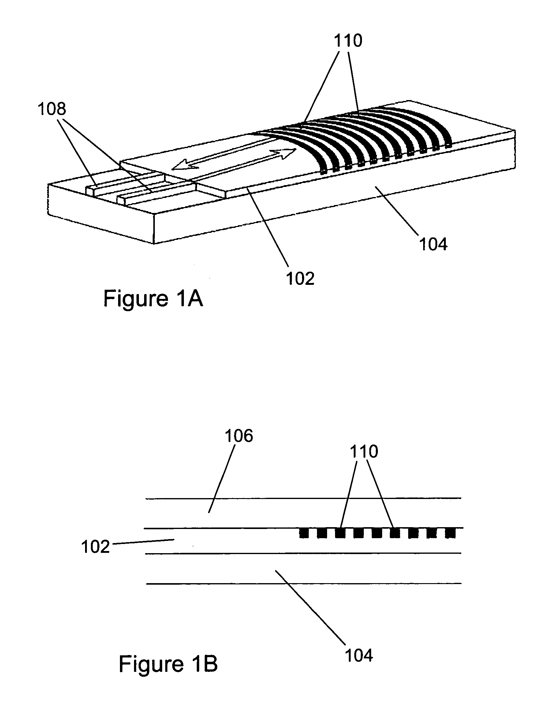
[0016]A planar optical waveguide is generally formed on or from a substantially planar substrate of some sort, which may be substantially flat or may be somewhat curved, bent, or deformed. The confined optical signals typically propagate as transverse optical modes supported or guided by the planar waveguide. These optical modes are particular solutions of the electromagnetic field equations in the space occupied by the waveguide, with each mode being characterized by its respective amplitude variation along the confined dimension. The planar waveguide may comprise a slab waveguide (substantially confining in one transverse dimension an optical signal propagating in two dimensions therein), or may comprise a channel waveguide (substantially confining in two transverse dimension an optical signal propagating in one dimension therein). It should be noted that the term “planar waveguide” is not used consistently in the literature; for the purposes of the present disclosure and / or appen...


PUM


Abstract

An optical time delay apparatus comprises: a multi-wavelength optical source; a diffractive element set imparting a wavelength-dependent delay on signals routed from the source to a 1×N optical switch; and N diffractive element sets routing signals from the 1×N switch to an output port. The optical propagation delay between the source and the output port varies according to the operational state of the source and the 1×N switch. A photodetector may receive the time-delayed signal at the output port.

Description

BENEFIT CLAIMS TO RELATED APPLICATIONS[0001]This application claims benefit of prior-filed now abandoned provisional App. No. 60 / 580,625 filed Jun. 16, 2004 in the names of Christoph M. Greiner, Thomas W. Mossberg, and Dmitri Iazikov, said provisional application being hereby incorporated by reference as if fully set forth herein.BACKGROUND[0002]The field of the present disclosure relates to optical time delay apparatus. In particular, optical time delay apparatus are described herein that incorporate diffractive element sets.[0003]One or more distributed optical structures (i.e., sets of diffractive elements) in a channel waveguide, an optical fiber, a slab waveguide, or another guided-wave optical structure may be used in a variety of devices for beam steering, spectral filtering, laser frequency control, spectral multiplexing, optical sensing, optical delay, or other functions. It is often desirable that such devices be optimized, or nearly so, for routing, mapping, or coupling o...

Claims


Application Information

Patent Timeline
Patent Type & Authority Patents(United States)
IPC IPC(8): G02B6/34H04J14/00
CPCG02B6/12007H04J14/02H04J14/005G02B6/2861
Inventor GREINER, CHRISTOPH M.MOSSBERG, THOMAS W.IAZIKOV, DMITRI
Owner STEYPHI SERVICES DE
Why Eureka
Try Eureka