
Sensor and method of sensing

a sensing and sensor technology, applied in the direction of fibre optic/optical waveguide device testing, reflectometer using simulated back-scatter, structural/machine measurement, etc., can solve the problem of scattering-based sensing system suffering, limiting the maximal sensing range and measurement accuracy, and stimulating brillouin

Active Publication Date: 2014-06-05
OMNISENS
View PDF3 Cites 14 Cited by
  • Summary
  • Abstract
  • Description
  • Claims
  • Application Information

AI Technical Summary

Benefits of technology

This patent text describes a method for improving the sensing of properties of a structure by using an optical fiber. A pump signal is propagated through a third optical propagation path and then amplified before being sent back to the second optical propagation path where it is used as a pump signal for sensing the properties of the structure. This amplified pump signal has greater power and is less affected by noise, resulting in more accurate sensing of the structure. Additionally, the method prevents amplification of signals in the first optical propagation path, which reduces the impact of noise and ensures sensing accuracy.

Problems solved by technology

Any stimulated Brillouin scattering-based sensing system suffers from two fundamental limitations, which restrict the maximal sensing range and the measurement accuracy.
The first limitation is the inevitable fiber intrinsic loss, showing a typical value of 0.2 dB / km in a standard single mode fiber at a wavelength of 1550 nm.
However, the associated nonlinear phenomena such as modulation instability and Raman amplification due to the high intensity will deplete the pump itself and limit the maximal input pump power.
Practically, this limits the range over which sensing can take place to about 30 km to 50 km.
The second limitation results from the depletion of the pump signal in large gain regime, that is a non-linear transfer of the pump power to the probe power taking place over a short distance and biasing the measurement.
However, it turns out that this configuration leads to a pump depletion that will make the sensing system nonlinear, and therefore not suitable for certain applications.
This also increase cost by a factor two.
The implementation of such a coding requires no modification of the hardware of the device, just a change in the software driving the device and a substantial overhead in calculations, so that it can be seen like an upgrade at a very low added cost.
However, SIMPLEX code is efficient if it is composed by “return to zero” (RZ) signals, which are more difficult to manage then “non return to zero” (NRZ) signals which limits its practicality.
However, the spontaneous noise generated from Raman amplifiers may impair the sensing system.
The intrinsic fiber loss is currently regarded as an inevitable bottleneck in any optical telecommunication link.
This causes a significant increase of beat-error-ratio (BER), hence a degradation of the signal fidelity.
The corresponding effect, for instance in Brillouin based sensing application, is a gradual exponential decrease of the power of the pump signal whilst it propagates through a sensing fiber; this results in a decrease of the back-scattered signal amplitude, so that the back-scattered signal becomes too weak to deliver reliable information.
Otherwise, the amplified probe will lead to depletion of the pump signal, and result in non-linear behaviour of the pump signal.
Brillouin pump repeaters can be used to compensate for the gradual exponential decrease of the power of the Brillouin pump as it propagates through the sensing fiber, but Brillouin pump repeaters are not sufficient to enable sensing over long distances.
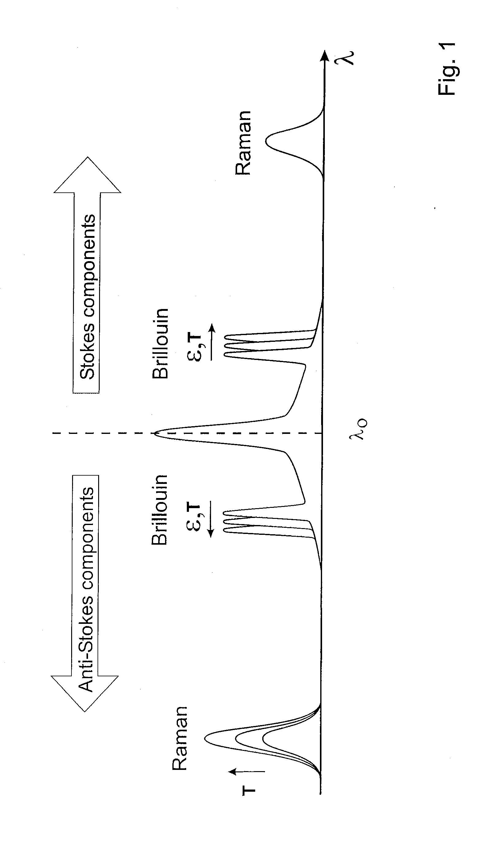
These two waves are spectrally so close to the pump signal that it is practically impossible to filter them out using a commercial optical filter.
In fact, the amplified spontaneous Brillouin Stokes and anti-Stokes waves lead to critical impairments of the function of the sensor system, by raising nonlinear parametric processes such as additional stimulated Brillouin interactions and four wave mixing process.

Method used


Image

  • Sensor and method of sensing
  • Sensor and method of sensing
  • Sensor and method of sensing

Examples


Embodiment Construction

[0101]FIG. 4 illustrates a sensor 20 according to one possible embodiment of the present invention. The sensor 20 is suitable for sensing one or more properties of one or more structures; in the particular example the sensor 20 is used for sensing the temperature and strain of a first and second pipe 21,37.

[0102]The sensor 20 comprises a first optical propagation path 23 which is defined by a first optical fiber 24. The first optical fiber 24 is secured to a surface 25 of the first pipe 21 to ensure that changes in the temperature and strain of the first pipe 21 will influence the propagation properties of the first optical fiber 24. A second optical propagation path 26 which is defined by a second optical fiber 29, is further provided. The second optical fiber 26 secured to a surface 28 of the second pipe 37 to ensure that changes in the temperature and strain of the second pipe 37 will influence the propagation properties of the second optical fiber 24.

[0103]The sensor 20 further ...


PUM

PropertyMeasurementUnit
Brillouin frequency shiftaaaaaaaaaa
optical propagation pathaaaaaaaaaa
opticalaaaaaaaaaa

Abstract

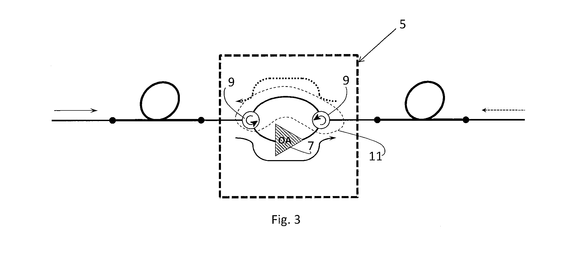
According to the invention, these aims are achieved by means of a sensor, suitable for sensing one or more properties of one or more structures, the sensor comprising, a first optical propagation path which is configurable to cooperate with a structure whose properties are to be sensed; a second optical propagation path which is configurable to cooperate with a structure whose properties are to be sensed; a third optical propagation path; a means for amplifying a signal which propagates in the third optical propagation path, so that the signal is amplified before it begins propagation along the second optical propagation path, and a means to prevent the propagation of signals from the second optical propagation path to the third optical propagation path. There is further provided a corresponding method of sensing.

Description

FIELD OF THE INVENTION[0001]The present invention concerns a sensor and method of sensing, and particular, but not exclusively to a sensor and method of sensing which measures properties of one or more structures using Brillouin scattering techniques.DESCRIPTION OF RELATED ART[0002]In many fields of application, like pipeline, power cables or subsea, the use of measuring apparatuses to monitor continuously structural and / or functional parameters is well known. The measuring apparatuses can be applied also to the civil engineering sector, and in particular in the field of the construction of structures of great dimensions.[0003]The measuring apparatuses are commonly used to control the trend over time of the temperature or of the strain, i.e. of the geometrical measure of the deformation or elongation resulting from stresses and defining the amount of stretch or compression along the fibre, of the respective structure. In more detail, these measuring apparatuses are suitable to give ...

Claims


Application Information

Patent Timeline
Patent Type & Authority Applications(United States)
IPC IPC(8): G01N21/88
CPCG01M11/085G01D5/35364G01M11/319G01L1/242G01M11/39G01N21/8806
Inventor GOSTELI, JULIENRAVET, FABIENROCHAT, ETIENNE
Owner OMNISENS
Learn More