Method for the manufacture of a vaned diffuser

a vaned diffuser and manufacturing method technology, applied in the direction of forging/pressing/hammering equipment, foundry patterns, forging moulding equipment, etc., can solve the problem of producing the required high-quality surface, achieve high surface quality, facilitate casting, machining, and finishing, and facilitate the delivery of molten metal

Inactive Publication Date: 2007-03-20
BORGWARNER INC
View PDF18 Cites 7 Cited by
  • Summary
  • Abstract
  • Description
  • Claims
  • Application Information

AI Technical Summary

Benefits of technology

[0020]The present invention is directed to an improved method for the manufacture of a vaned diffuser, as used within the compressor stage of a turbocharger, which is suited for high volume production. The casting method of the present invention is also useful for the casting of other types of non-ferrous part comprising fine vanes or projections where such a part also possess an axis for direct pulling of the part, and where precision dimensions and high surface quality as is provided by casting in plaster, are desired.
[0021]In accordance with a first embodiment of the invention, there is provided a method for the manufacture of a non-ferrous vaned diffuser, preferably from aluminum. In this method, a male metallic template of a vaned diffuser is first prepared that includes a) a central portion comprising a hub that facilitates casting, machining, and finishing of the diffuser, and (b) at least the upper surface of the vaned diffuser comprising the vanes. A female plaster mold is cast from the male metallic template by applying a plaster slurry to the male template and allowing the plaster to dry and harden within a suitable frame. The hardened female plaster mold is then separated from the male template along the translational axis corresponding to the central hub axis, and herein termed the “pullable axis.” Molten metal, preferably non-ferrous metal or alloy having a melting point of less than about 700° C., more preferably molten aluminum, is introduced into the plaster female mold assisted by evacuation of the plaster mold, and the metal is then permitted to cool and solidify. The metal vaned diffuser casting is pulled to separate it from the plaster cast along the pullable axis or translational axis corresponding to the central hub axis. Finally, machine finishing removes the hub and to yield the near-net vaned diffuser, which may be finished by conventional means.
[0022]In a second embodiment of the method of the present invention, the hub of the male metallic template further comprises a plurality of ribs radially disposed about the hub. These ribs facilitate the delivery of molten metal to the vane castings and reduce ringing of the metal casting during machining by increasing the natural frequency of the casting. In this embodiment, it is preferred to provide a gap between the ribs and the vanes sufficient to permit separation of the finished ring diffuser from the hub without the necessity of machining through the ribs.

Problems solved by technology

Those of ordinary skill in the art would have foreseen difficulties in producing the required high-quality surface finish, in achieving the close dimensional tolerances required, in successfully flowing the liquid material through the relatively long and thin blade casting channels, and in separating such a vaned diffuser from its cast without damage.

Method used


Image

  • Method for the manufacture of a vaned diffuser
  • Method for the manufacture of a vaned diffuser
  • Method for the manufacture of a vaned diffuser

Examples


Embodiment Construction

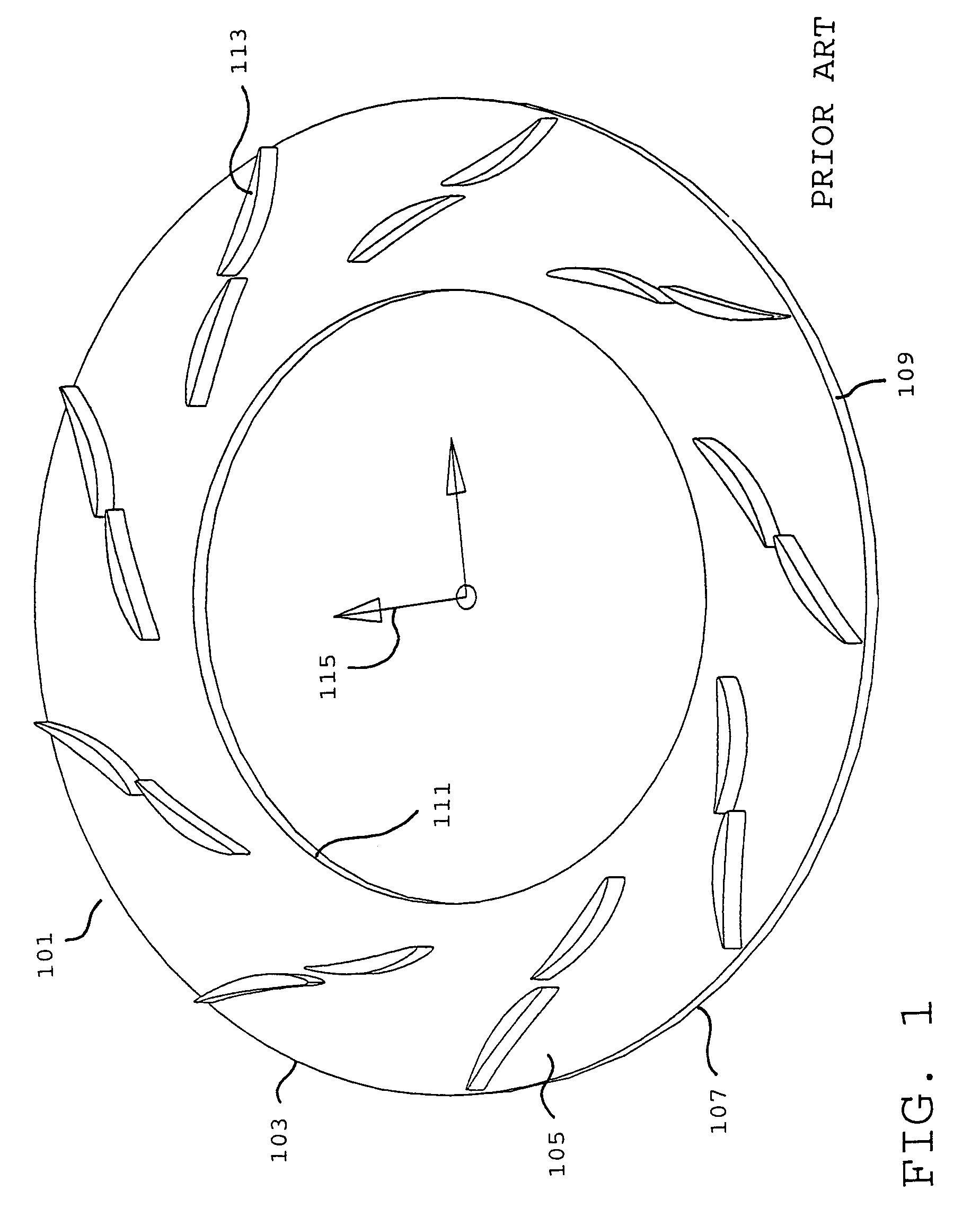
[0029]For the purpose of illustrating the method steps of the present invention, FIG. 1 illustrates a vaned diffuser 101, which is known in the prior art to be produced by machining from solid metal, but production of which is described herein according to the method of the present invention. The vaned diffuser comprises a essentially disc-shaped portion 103, having an approximately flat upper surface 105 and an approximately flat lower surface 107, which is essentially parallel to the upper surface, and also having an outer circumferential edge 109 and an inner circumferential edge 111. From the upper surface 105 of the disc, a plurality of vanes 113 extend approximately perpendicularly from said surface 105. The vanes 113 are positioned, in the assembled turbocharger, to accept high velocity air from a compressor wheel located approximately within the inner circumferential edge 111 of the diffuser, and rotating about a central perpendicular axis 115.

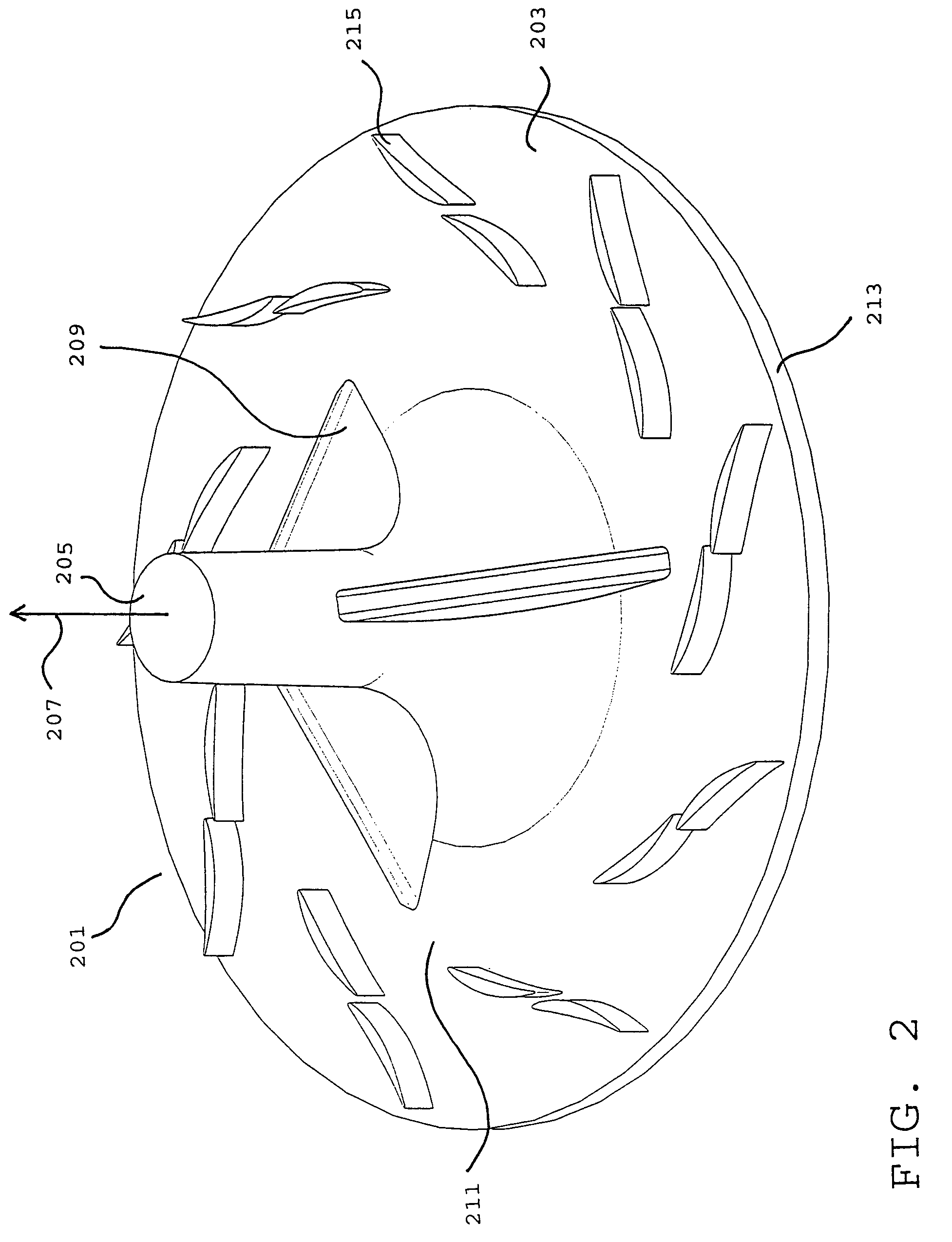
[0030]Referring now to FIG. 2, ...


PUM

PropertyMeasurementUnit
melting pointaaaaaaaaaa
diameteraaaaaaaaaa
velocityaaaaaaaaaa

Abstract

An improved method for manufacturing a vaned diffuser (101) of a turbocharger, preferably from aluminum or an aluminum alloy, where the vaned diffuser possesses at least one axis (115) suitable for separating the vaned diffuser from its rigid mold by translation. Casting of a raw vaned diffuser (407) having an optional central hub (205) and, optionally, ribs on the hub (209), is disclosed in a plaster mold (305). The hub and optional ribs are machine finished from the raw vaned diffuser to yield the finished vaned diffuser (101). The method provides the high degree of dimensional accuracy, and high quality surface finish, required to produce a vaned diffuser of an efficient turbocharger.

Description

FIELD OF THE INVENTION[0001]The present invention relates to an improved method for the manufacture of a vaned diffuser of a type-used in an exhaust driven turbocharger to accept high-velocity air from a compressor wheel and provide pressurized air to an internal combustion engine. Specifically, the invention relates to an improved method for the manufacture of a vaned diffuser having a complex geometry and a pullable axis. The method further relates to a casting process that provides a vaned diffuser having high degree of dimensional trueness, repeatable manufacture, and a high quality surface finish, compared to conventional machining of a vaned diffuser from solid metal.DESCRIPTION OF THE RELATED ART[0002]Turbochargers are widely used in internal combustion engines to increase engine power and efficiency, particularly in the large diesel engines of highway trucks and marine engines. It is particularly advantageous in these types of engines to use turbochargers that are designed t...

Claims


Application Information

Patent Timeline
Patent Type & Authority Patents(United States)
IPC IPC(8): B23P15/00B22D29/00B23P15/02B22C9/04B22D25/02F04D29/44
CPCB22C9/04B22D25/02B22D29/00B23P15/006F04D29/444Y10T29/49321Y10T29/49989Y10T29/49988Y10T29/4932F04D29/023F05D2230/21F05D2250/52F05D2300/121F05D2300/173
Inventor ROBY, STEVE
Owner BORGWARNER INC
Why Eureka
Try Eureka