
Method and apparatus for solid-stranding a flextube unit

Inactive Publication Date: 2007-03-20
DRAKA COMTEQ BV
View PDF56 Cites 6 Cited by
  • Summary
  • Abstract
  • Description
  • Claims
  • Application Information

AI Technical Summary

Benefits of technology

[0017]An object of the present invention is to overcome the disadvantages of the related art. In particular, it is an object of the present invention to increase line speed and decrease cost in the production and use of flextube units, or optical cables.
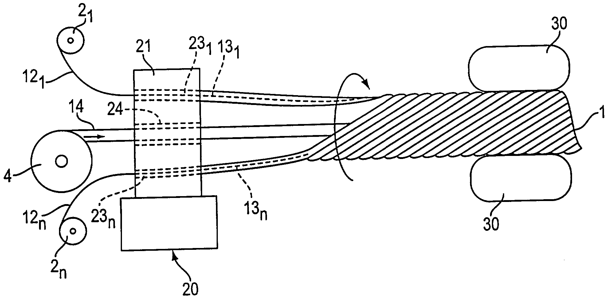
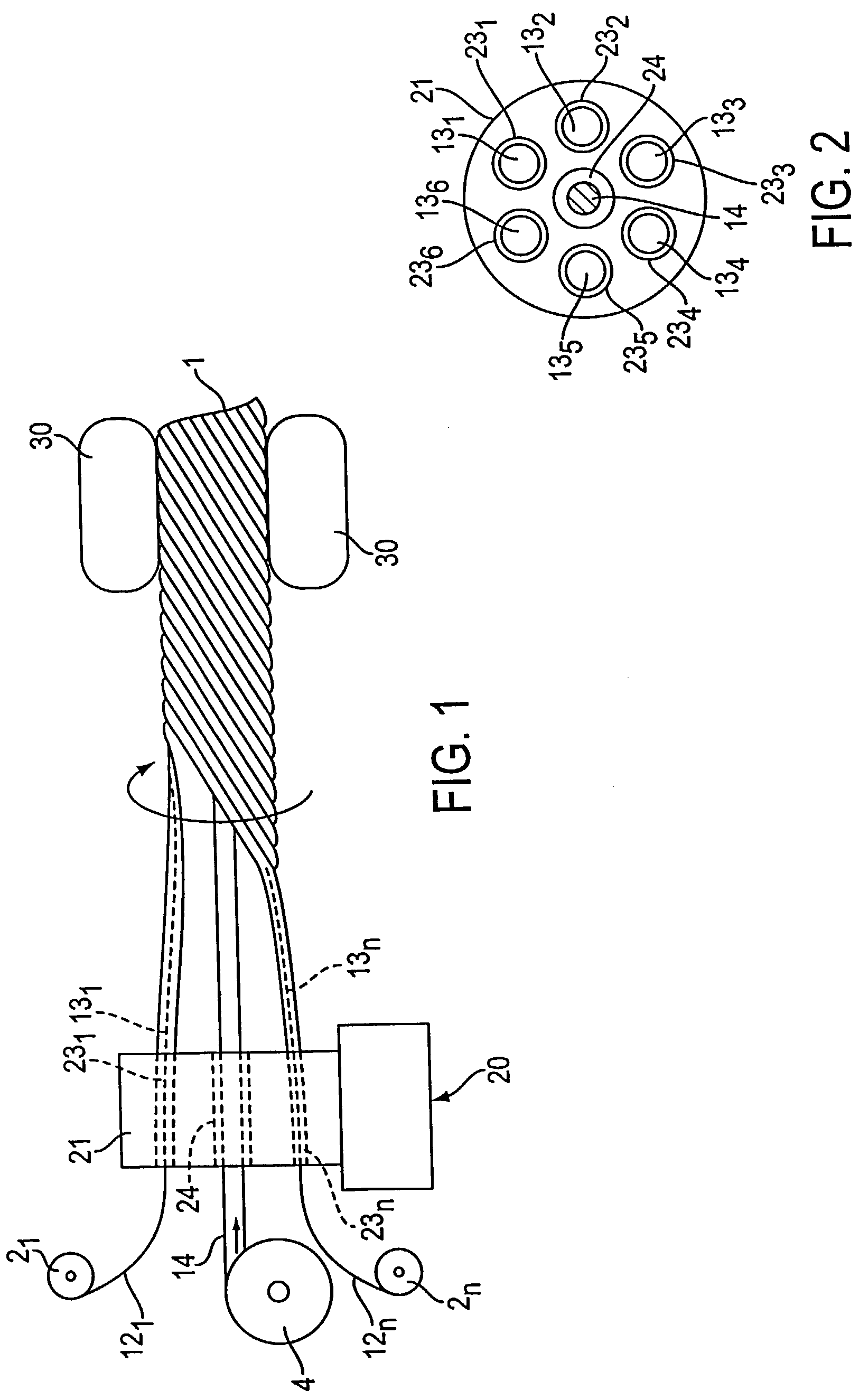
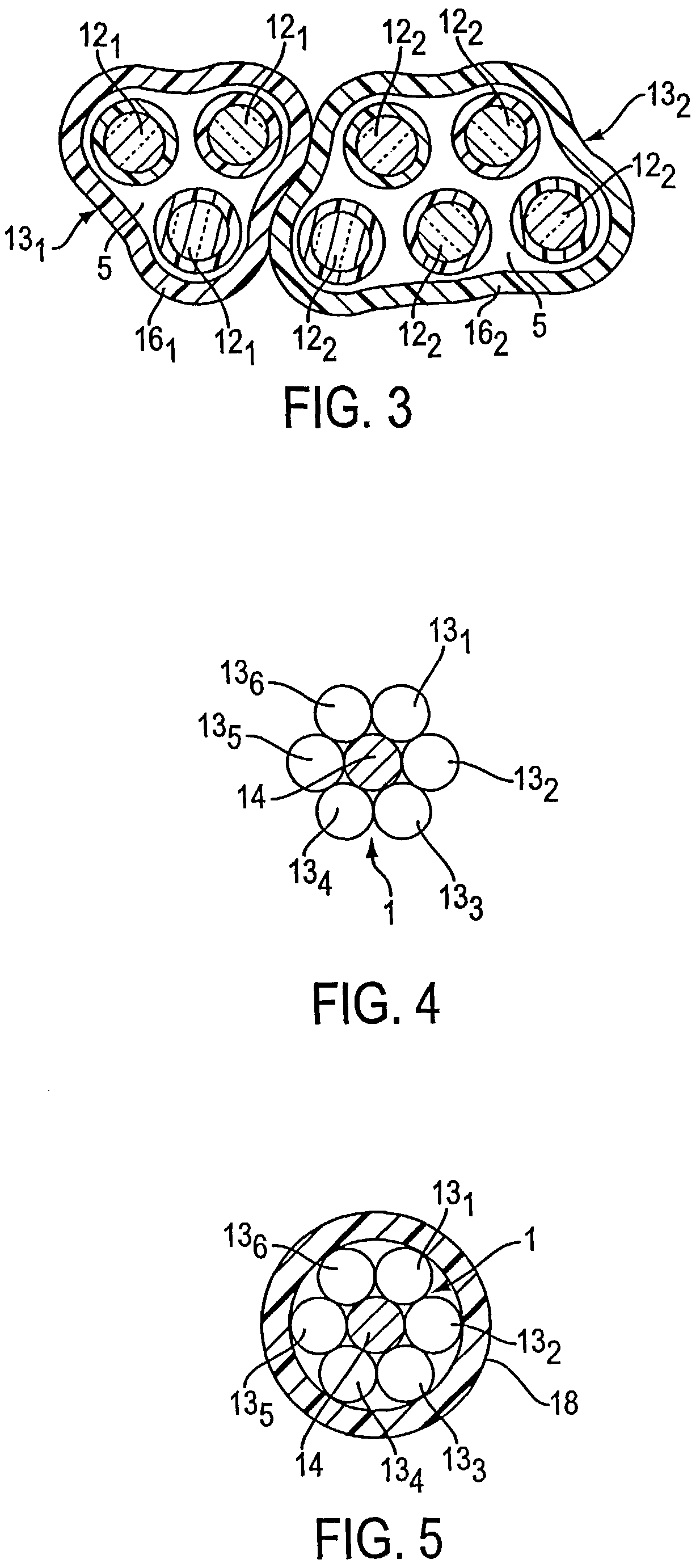
[0018]The present invention achieves the above and other objects and advantages by providing a new process, in manufacturing optical cables, called solid-stranding. The process of solid-stranding is a one-step process for extruding multiple loose tubes or flextubes (hereinafter simply referred to as flextubes for convenience) and stranding the tubes in helical or SZ stranded arrangement prior to winding the optical cable on a take-up reel. The method and apparatus of the present invention, for solid-stranding, combine together buffering and stranding operations, as well as perform the stranding operation while the supporting sheaths of the flextubes are still hot so that they adhere together without additional binders. In particular, optical fibers and / or wires are supplied to an extruder which forms supporting sheaths around individual ones or groups of the optical fibers and / or wires. A central element is supplied through the center of the extruder. A rotating pulling device, such as a caterpillar, helically strands the flextubes around the central element as the sheaths cool down. That is, in the new solid-stranding process of the present invention, buffering and stranding operations are performed together without a cooling stage therebetween so that the flextubes contact one another and the central element at a temperature which is between the process temperature and the melting point of the material from which the flextubes are made. The process temperature is that of the material in the extruding die and, typically, is 20–50° C. above that material's melting point, wherein the melting point is typically a range of temperatures over which the material melts. Although the melting point is actually a range of temperatures over which the material melts, the term “melting point” is used for convenience. Thus, because the flextubes are brought together at a temperature which is between the process temperature and the melting point, they adhere together forming a composite core. The composite core then may be jacketed by passing through another extruder, or may be used without a jacket, thereby forming a flextube unit from which individual flextubes easily may be split.
[0019]Because there is no need to completely cool the flextubes before they are stranded, and the flextubes have a relatively thin supporting sheath wall, water cooling of individual flextubes can be replaced by air cooling the composite core. That is, cooling water right after extrusion becomes unnecessary. Therefore, any water swellable elements used in the flextube unit are not damaged. Additionally, air cooling—as opposed to water cooling—the flextubes may help to improve the breakability and split of the supporting sheath, when it is desired to do so. That is, water cooling may undesirably change the mechanical behavior of some polymers, like those based on polypropylene (PP). Such undesirable change in mechanical behavior is eliminated by air cooling the flextubes after they have been stranded together.
[0020]Further, solid-stranding—wherein buffering and stranding are performed in the same process—shortens manufacturing time. That is, skipping the cooling stage—wherein individual flextubes are formed, which must then be combined in a stranding phase—increases production speed.
[0021]Moreover, solid-stranding forms a composite core which eliminates the need for separate binders to hold the flextubes together. Conventional cable designs produced by separate buffering and stranding processes may use a minimum of one binder—typically a polyester yarn—to secure all the loose tubes or flextubes during the tube stranding step. The binder allows the tubes to remain at desirable locations, such as in helically or SZ-stranded arrangements. However, the binders add costs in manufacturing material and equipment, as well as labor burden in the field to remove the binder prior to accessing the tubes. Because separate binders are not necessary in the solid-stranding process of the present invention, production speed is further increased and, at the same time, production cost is reduced. Further, such results in a lower cost optical cable, the tubes and optical fibers of which can be more easily accessed in the field thereby reducing labor costs involved with use and repair of the optical cable.
[0022]The solid-stranded flextubes may be continuously helically stranded in one direction, or may change stranding directions to form an SZ-stranded composite core. Further, the central element may be a water swellable yarn, a ripcord, or itself may be a flextube having optical fibers therein. Alternatively, the central element may be a metallic or other heat conducting member. In this case, the central element can be heated to further promote adhesion between the flextubes stranded around it, as well as to assist in sticking the flextubes to the central member.

Problems solved by technology

That is, cooling water right after extrusion becomes unnecessary.
That is, water cooling may undesirably change the mechanical behavior of some polymers, like those based on polypropylene (PP).
Further, solid-stranding—wherein buffering and stranding are performed in the same process—shortens manufacturing time.

Method used


Image

  • Method and apparatus for solid-stranding a flextube unit
  • Method and apparatus for solid-stranding a flextube unit
  • Method and apparatus for solid-stranding a flextube unit

Examples


Embodiment Construction

[0033]The method and apparatus of the present invention are directed to a new and novel solid-stranding process. The solid-stranding process of the present invention combines buffering and stranding operations, as well as performs stranding while the flextubes 131–13n are still hot so that they adhere together without additional binders, thereby producing a solid-stranded flextube unit. The flextubes 131–13n are formed by optical fibers 121–12n that are supplied to an extruder 20, and supporting sheaths (also called flextube walls) 161–16n formed by the extruder 20 around individual ones or groups of the optical fibers 121–12n. A central element 14 is supplied through the center of the extruder's head 21. A rotating pulling device, such as a caterpillar 30, helically strands the flextubes 131–13n around the central element 14 as the flextubes 131–13n cool down. That is, in the solid-stranding process of the present invention, buffering and stranding operations are performed together...


PUM

PropertyMeasurementUnit
Temperatureaaaaaaaaaa
Melting pointaaaaaaaaaa

Abstract

A solid-stranding method and apparatus for forming optical cables. Solid-stranding combines buffering and stranding operations, as well as performs the stranding operation while the flextubes are still hot so that they adhere together without additional binders. Optical fibers and / or wires are supplied to an extruder which forms flextubes around individual ones or groups of the optical fibers and / or wires. A central element may be supplied to, and go through, the center of the extruder. A rotating pulling device, such as a caterpillar, helically or in an SZ-manner solid-strands the flextubes around the central element—or solid-strands the flextubes to themselves when no central element is present—as the flextubes cool down. That is, solid-stranding includes buffering and stranding operations that are performed together without a water cooling stage therebetween. Thus, the flextubes adhere together, and may adhere to the central member, thereby forming a solid-stranded composite core. The solid-stranded composite core then may be jacketed by passing through another extruder, or may be used without a jacket, thereby forming a solid-stranded flextube unit from which individual flextubes easily may be split.

Description

[0001]This is a divisional of Application Ser. No. 09 / 576,173, filed May 23, 2000 now U.S. Pat. No. 6,584,251; the disclosure of which is incorporated herein by reference.BACKGROUND[0002]1. Field of the Invention[0003]The present invention is directed to a method and apparatus for manufacturing optical cables and, in particular, optical cables which include flextubes having optical-fibers therein.[0004]With the advent of local area networks and the relative broadband capabilities of fiber optic links, it has become commonplace for new communication systems to include fiber-optic capabilities. Communication cables employing optical fibers—optical cables—are widely used in the telecommunications industry. In particular, multifiber optical cables are widely used for long distance telephone communications, interexchange telephone applications, and other telephony and data transmission applications. Optical cables are also being incorporated into cable television networks in place of mor...

Claims


Application Information

Patent Timeline
IPC IPC(8): B29C47/02G02B6/44
CPCG02B6/449
Inventor ARDOUIN, PASCAL
Owner DRAKA COMTEQ BV
Learn More