EPI-illumination system for an array microscope

an array microscope and epi-illumination technology, applied in the field of microscopy, can solve the problems of ineffective use of dia-illumination, present new challenges for illumination, and prior art epi-illumination techniques cannot be used

Inactive Publication Date: 2007-03-20
DMETRIX INC
View PDF10 Cites 21 Cited by
  • Summary
  • Abstract
  • Description
  • Claims
  • Application Information

AI Technical Summary

Benefits of technology

[0009]The present invention meets the challenge of providing epi-illumination in an array microscope by placing the light source, directly or virtually, at the pupil of individual microscope elements on the optical axis thereof where the light source has negligible affect on the image, or at the plan conjugate with the object, and by taking advantage of support material between imaging elements in an array thereof to provide illumination optical elements, thereby permitting standard illumination concepts to be applied in a novel way to accommodate an array microscope. For Kohler illumination, illumination light sources are placed at the pupils of respective individual microscope elements. In one Kohler illumination embodiment, the light source is a point source comprising the tip of an optical fiber placed on the optical axis at the pupil of its corresponding microscope element. In another Kohler illumination embodiment, the illumination light is provided by a reflective boundary in a light guide placed on the optical axis of a corresponding microscope element. For critical illumination the light sources are placed at locations conjugate with their respective object planes so as to image the light sources thereon. This configuration is particularly suitable for confocal microscopy. For dark-field illumination, the support material around a microscope lens, which is used to support an array of lenses, is fashioned to form an illumination optical element so that light from an off-axis source is directed by the illumination element toward the object plane at an angle such that light will no be reflected into the field of view of the imaging system but scattered or fluorescence light will be within that field of view. The illumination optical element may be a refractive element, a Fresnel lens, a reflective element, a diffractive element, or some combination of one or more of these elements. An array of pinhole apertures may be provided to operate the array microscope in a confocal mode. All of the embodiments may be used for epi-fluorescence microscopy.

Problems solved by technology

The recent development of array microscopes, also known as miniaturized microscope arrays, presents new challenges for illumination.
Indeed, the multiplicity of lenslets arranged in an array and the small dimensions of the array suggest that prior art epi-illumination techniques cannot be used.
Yet, a principal application for array microscopes is to image specimens, such as biological microarrays for protein analysis that are sufficiently opaque that dia-illumination cannot be used effectively.
Accordingly, there is an unfulfilled need for methods and devices for providing epi-illumination of objects to be imaged by array microscopes using epi-illumination.

Method used


Image

  • EPI-illumination system for an array microscope
  • EPI-illumination system for an array microscope
  • EPI-illumination system for an array microscope

Examples


first embodiment

[0039]Turning to FIG. 5, Kohler illumination employs an optical fiber 52 whose exit port 54 is placed substantially on the optical axis of the imaging system and in the plane of the system pupil, that is, the focal plane of first lens 14, so as to emit light toward the object. FIG. 6 shows a side view of the optical fiber 52. The protective cladding 58 of the fiber is stripped back and the tip 60 of the fiber is shaped so that light propagating down the fiber is reflected laterally when it reaches the tip, forming a cone of light 62 within the back side field view of the objective 14. The fiber obscures an insignificant portion of the pupil and does not alter the imaging properties of the optical system.

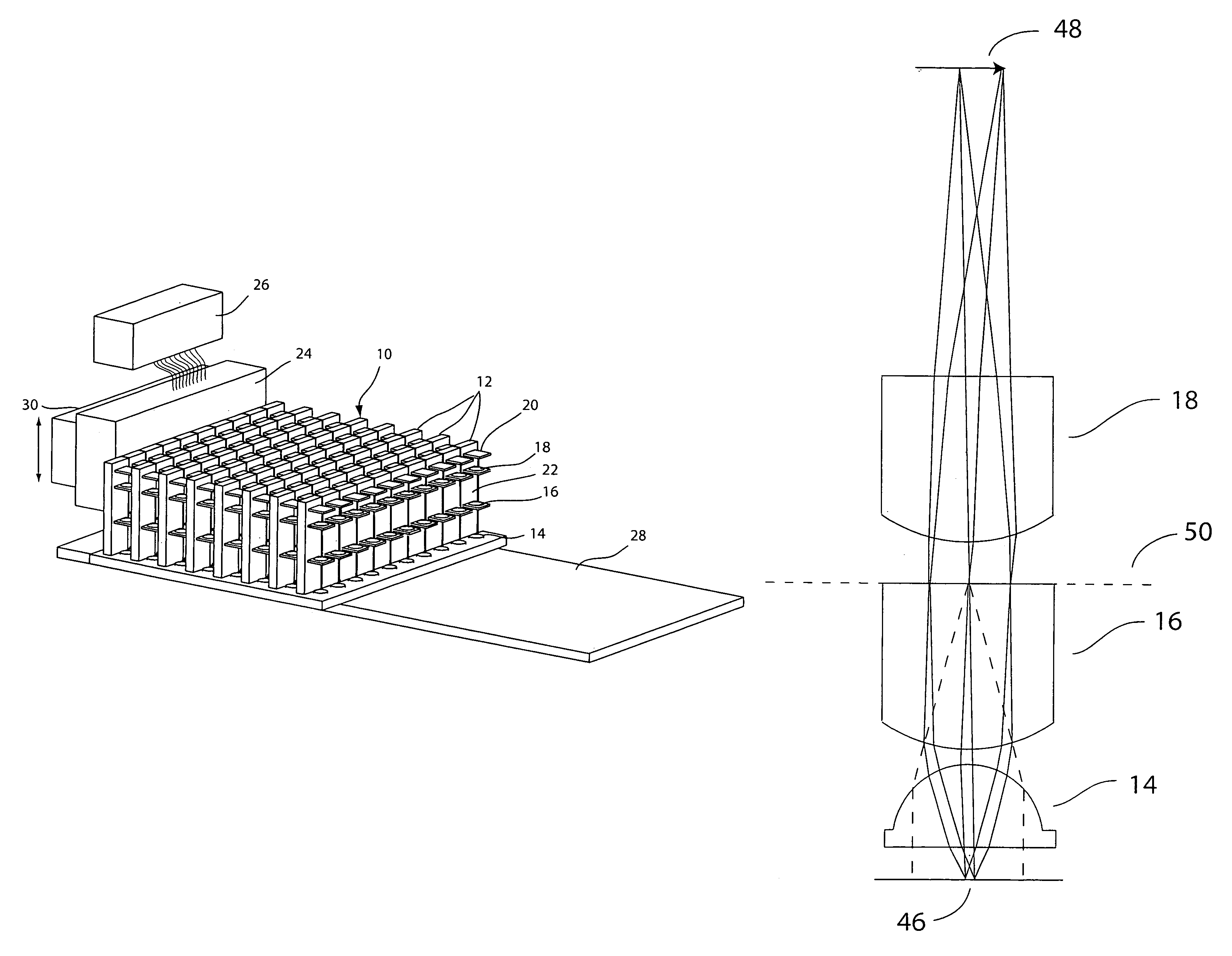
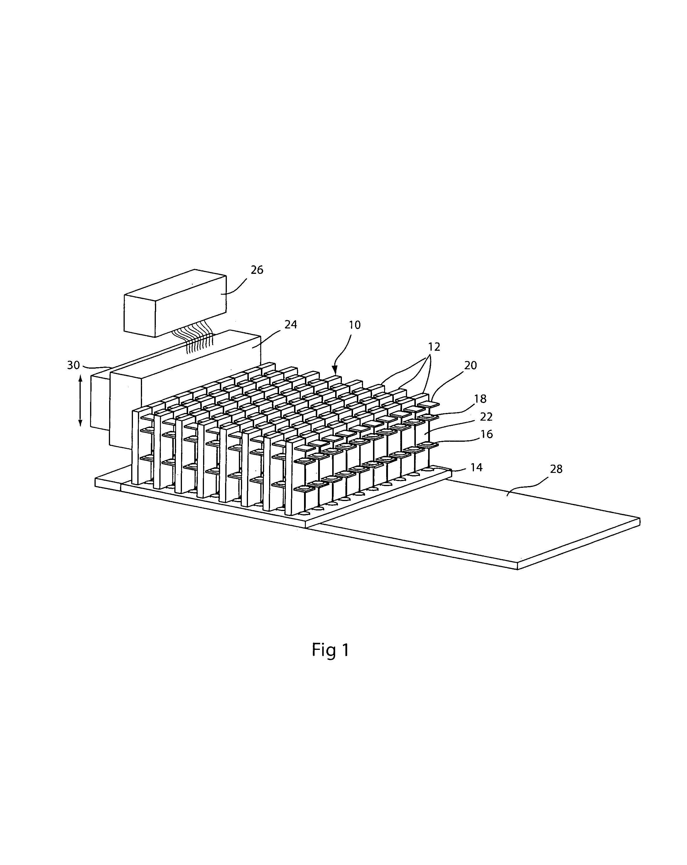
[0040]FIG. 7 shows another embodiment of Kohler illumination that is particularly well suited to an array microscope of the type shown in FIG. 2. Thus, in a system having a number of optical elements 14, 16 and 18 for imaging a portion of an object 46 to a detector 42, a light guide ...

embodiment 100

[0043]The ray trace diagram of FIG. 8 illustrates a general embodiment 100 of the invention for critical illumination. In an individual microscope element as show in FIG. 3, a beam splitter 102 is placed in the optical path of the individual microscope element so as to reflect light from a source 104 toward the object plane 106. The beam splitter and source are disposed between the lens 18 and an image plane 108. The source 104 is an extended source unless the microscope is used in a confocal mode. In any case, the source is placed at a virtual image plane 110 produced by the beam splitter 102 so that the extended source is imaged into the object plane 106 so as to produce critical illumination. A point source can be substituted for the extended source if the microscope is used in a confocal mode.

[0044]A first variation 110 of critical illumination in accordance with the general embodiment 100 can be implemented as shown in FIG. 9(a) by a single beam splitter 112 that interacts with...

embodiment 200

[0047]Turning to FIG. 12, a first, refractive embodiment 200 of dark-field illumination employs a first lens plate 202 which has, for each microscope element, in addition to a first lens 204 a refractive surface 206 in the peripheral space 208 around the first lens 204. One or more light sources 210 are disposed on the back side of the first lens plate 202 and illuminate points 212 on the object plane 102. Thus, all of the light from sources 210 captured by the field of view of the refractive surface 206 illuminates the object points 212, but at an angle such that the objective 204 will only collect light which has been scattered from that object point. In general, the sources 210 are extended sources that illuminate the entire field of view of the lens 204, but point sources can be used as well.

[0048]A second embodiment of dark field illumination 250 is shown in FIG. 13. It is a variation on the first embodiment shown in FIG. 12, in that, instead of a refractive surface in the peri...


PUM


Abstract

An epi-illumination system for an array microscope. For Kohler illumination, illumination light sources are placed, actually or virtually, at the pupils of respective individual microscope elements of an array microscope. In one Kohler illumination embodiment, the light source is a point source comprising the tip of an optical fiber placed on the optical axis at the pupil of its corresponding microscope element. In another Kohler illumination embodiment, the illumination light is provided by a reflective boundary placed on the optical axis of a corresponding microscope element. For critical illumination the light sources are placed at locations conjugate with their respective object planes so as to image the light sources thereon. For dark-field illumination, the support material around a microscope element lens, which is used to support an array of lenses, is fashioned to form an illumination optical element so that light from an off-axis source is directed by the illumination element toward the object plane at an angle such that light will not be reflected into the field of view of the imaging system, but scattered or fluorescence light will be within that field of view. The illumination optical element may be refractive element, a Fresnel element, a reflective element, a diffractive element, or some combination of one or more of these elements. An array of pinhole apertures may be provided to operate the array microscope in a confocal mode. All of the embodiments may be used for epi-fluorescence microscopy.

Description

FIELD OF THE INVENTION[0001]This invention relates to microscopy, and particularly to illumination systems for an array microscope comprising a plurality of optical imaging elements configured to image respective sections of an object and disposed with respect to an object plane so as to produce at respective image planes respective images of the respective sections of the object.BACKGROUND OF THE INVENTION[0002]In microscopy, adequate and appropriate illumination of the object to be imaged by a microscope is essential. There must be enough light provided to the object to permit a viewer or detector to discern features of the object in the image produced by the microscope. In addition, the manner in which the light is provided to the object makes a difference in what features can be detected and the contrast with which they are imaged. Fundamentally, if the object to be imaged is transparent, it can be illuminated so that light passes through it and is modulated by the features of t...

Claims


Application Information

Patent Timeline
Patent Type & Authority Patents(United States)
IPC IPC(8): G02B21/06G02B21/00G02B21/08G02B21/12
CPCG02B21/002G02B21/125G02B21/082Y10S359/90
Inventor OLSZAK, ARTUR G.LIANG, CHEN
Owner DMETRIX INC
Why Eureka
Try Eureka