Optical recording medium, method for recording on optical record medium, and apparatus for recording on optical record medium

Inactive Publication Date: 2007-03-20
PANASONIC CORP
View PDF19 Cites 69 Cited by
  • Summary
  • Abstract
  • Description
  • Claims
  • Application Information

AI Technical Summary

Benefits of technology

[0049]According to the present invention, in the optical recording medium having a plurality of information layers, in the case of mark length recording at high density, an independent recording condition can be set in each recording layer. Therefore, in all info

Problems solved by technology

However, when the space length is shorter, the heat at the trailing edge of the recorded mark has an effect on temperature rise at the leading edge of the mark to be recorded next, or the heat at the leading edge of the mark recorded next has an effect on the cooling process of the preceding mark, that is, so-called heat interference occurs.
By this heat interference, the edge position of the leading edge or trailing edge of the rec

Method used


Image

  • Optical recording medium, method for recording on optical record medium, and apparatus for recording on optical record medium
  • Optical recording medium, method for recording on optical record medium, and apparatus for recording on optical record medium
  • Optical recording medium, method for recording on optical record medium, and apparatus for recording on optical record medium

Examples


embodiment 1

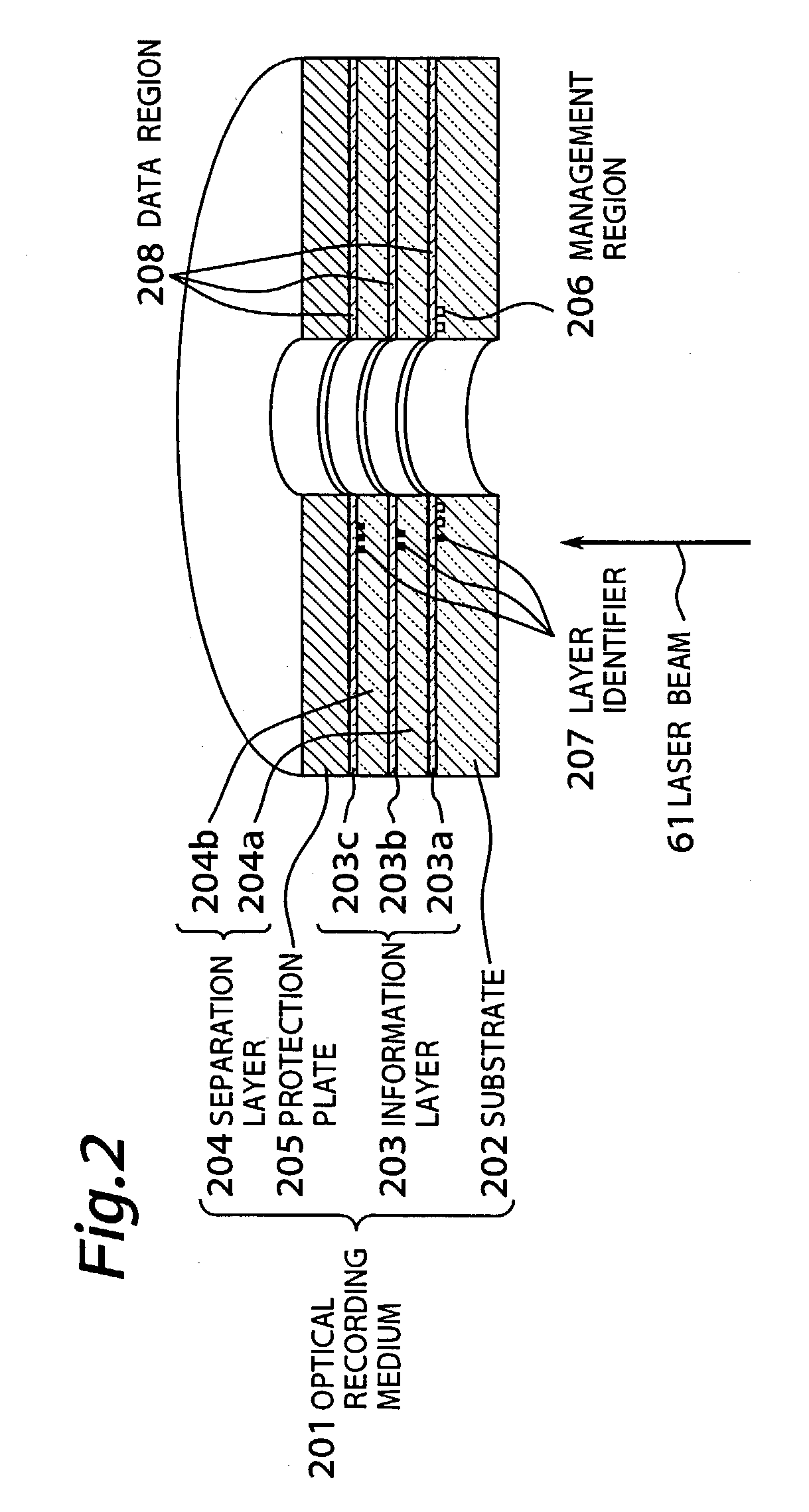
[0063]FIG. 2 is a sectional view showing an optical recording medium used in a first embodiment of the present invention. In FIG. 2 an optical recording medium 201 includes a plurality of information layers 203 (203a, 203b, 203c) formed on a substrate 202, and the individual information layers are separated by separation layers 204 (204a, 204b). In this embodiment, the multilayer recording layer is composed of, for example, three information layers 203.

[0064]The substrate 202 is made of polycarbonate or other resin material, or glass. On the surface of the substrate, various patterns are formed, such as guide tracks having a specific depth for tracking of beam, pits for address, or pits depending on the management information of the optical recording medium.

[0065]The material for composing the information layers 203a, 203b, 203c is available in two types, that is, the write-once type for recording only once, and the rewritable type for recording repeatedly. The write-once type recor...

embodiment 2

[0097]A second embodiment of the present invention is explained below. When recording in second and subsequent information layers from the light source side, the transmissivity of the information layer varies depending on whether the information layer of the light source layer is in recorded state or unrecorded state. Accordingly, the intensity of the laser beam reaching these information layers varies, and the recording condition at the leading edge and trailing edge may be changed. By contrast, in this embodiment, the independent leading edge recording condition and trailing edge recording condition are set depending on the recorded state of each layer closer to the light source side than the information layer to be recorded.

[0098]FIG. 5 is a sectional view of an optical recording medium. An optical recording medium 501 includes a substrate 202, an information layer 203, a separation layer 204, a protection plate 205, and a layer identifier 207, and the same one as in the first em...

embodiment 3

[0116]In order to correct the recording condition difference due to difference between optical recording media or difference between optical recording apparatuses, this embodiment proposes a method of determining optimum values by learning the leading edge position and trailing edge position of recording pulse in each information layer.

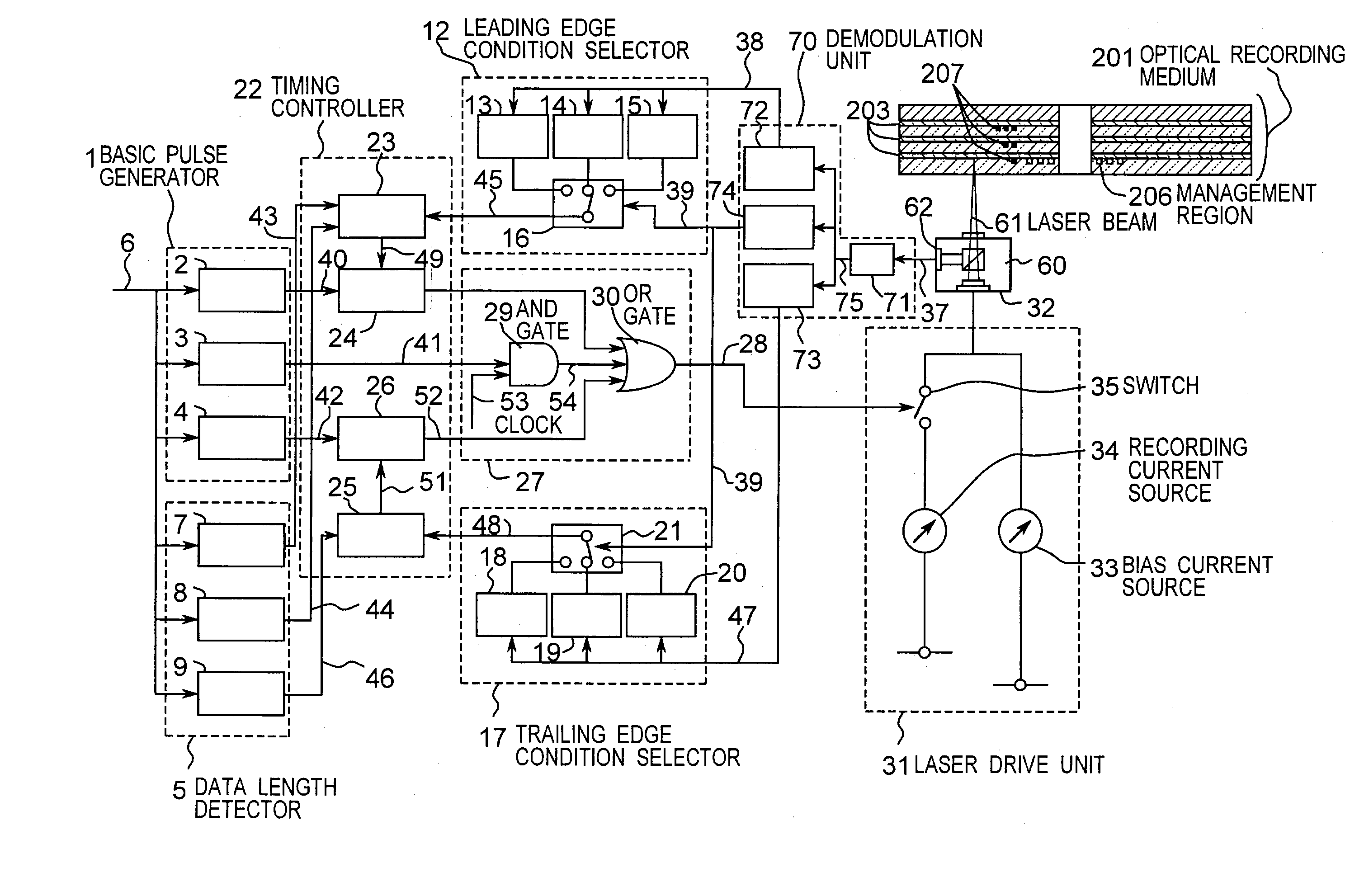
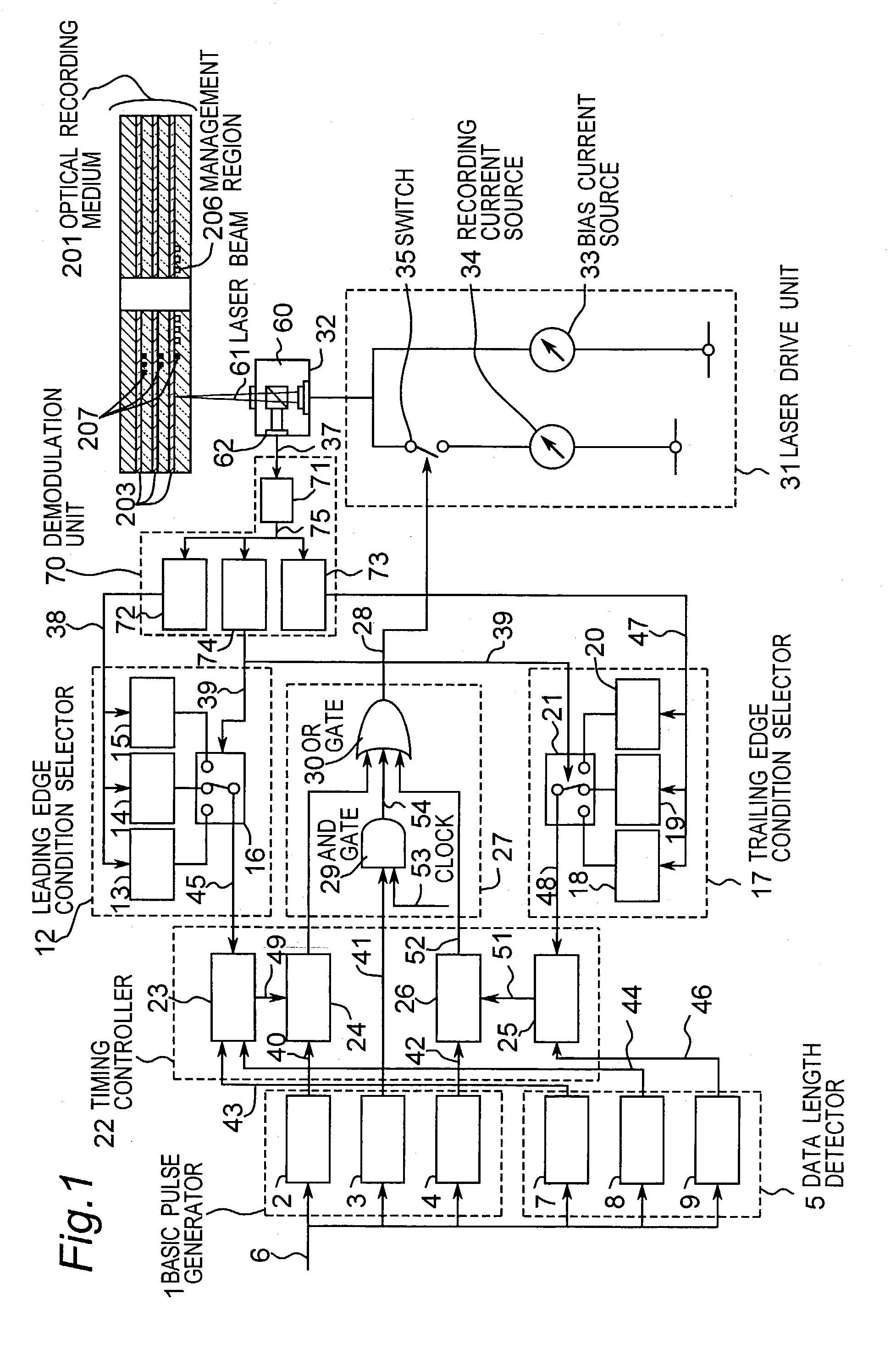
[0117]FIG. 6 is a diagram of sectional view of optical recording medium. Learning regions 601 are provided in the information layers 203a, 203b, 203c for determining the optimum values of delay amount of leading edge pulse and trailing edge pulse. A configuration of an apparatus for recording information in an optical recording medium 501 is shown in FIG. 8, in which a leading edge delay amount change circuit 801 is added to the leading edge pulse delay circuit 24 of the timing controller 22 in FIG. 1, and a trailing edge delay amount change circuit 802 is added to the trailing edge pulse delay circuit 25.

[0118]Referring to a flowchart in FIG. 7, we w...


PUM


Abstract

An optical recording medium of the present invention includes a substrate (202), a protection plate (205), and a plurality of information layers (203) sandwiched between the substrate and the protection plate. An information signal is recorded as a length of a mark and a length of a space between two marks. The mark is formed when the information layer is irradiated by light received through the substrate. The information layers have a management region (206) recording a leading edge recording condition and a trailing edge recording condition. The leading edge recording condition is used to change a recording start position for forming a leading edge of the mark. The trailing edge recording condition is used to change a recording end position for forming a trailing edge of the mark. Each of the leading and trailing edge recording condition is depending on which information layer is recorded.

Description

BACKGROUND OF THE INVENTION[0001]1. Technical Field[0002]The present invention relates to an optical recording medium and a recording and reproducing apparatus capable of recording or reproducing signals of high density by irradiating a plurality of thin recording films formed on a substrate with a high energy beam such as laser beam.[0003]2. Background Art[0004]Recently, commercialization of optical recording media capable of recording, erasing and reproducing information, and research and development of rewritable optical recording medium of high density capable of recording moving images of high quality are actively done. Known examples of rewritable optical recording media include the phase change optical recording medium having a disk-shaped substrate and an overlaying information layer such as a thin chalcogenide film using Te or Se as the base such as Ge—Sb—Te or In—Se, or a semimetallic thin film such as In—Sb. A magneto-optical recording medium having a thin metal film of F...

Claims


Application Information

Patent Timeline
IPC IPC(8): G11B7/0045G11B7/00G11B7/007G11B7/013G11B7/125
CPCG11B7/0045G11B7/00456G11B7/007G11B7/1267G11B7/24085G11B7/00736G11B2007/0013G11B7/24038
Inventor FURUKAWA, SHIGEAKINISHIUCHI, KENICHIAKIYAMA, TETSUYANARUMI, KENJI
Owner PANASONIC CORP
Why Eureka
Try Eureka