
Method and apparatus for designing and developing a vehicular damper

Inactive Publication Date: 2007-03-20
FORD GLOBAL TECH LLC
View PDF13 Cites 11 Cited by
  • Summary
  • Abstract
  • Description
  • Claims
  • Application Information

AI Technical Summary

Benefits of technology

[0009]It is a first non-limiting advantage of the present invention to provide a method and an apparatus for designing and developing a vehicular damper in a manner which overcomes some or all of the previously delineated drawbacks associated with prior vehicular damper strategies, techniques, and methodologies.

Problems solved by technology

The design process is further complicated by the use of many diverse types of engines, transmissions and other components which generally require unique types of dampers to achieve the foregoing desired benefits (e.g., each unique combination of these components may require a unique damper design).
While the foregoing design process does allow for the creation of a desirable damper prototype, it is costly and is significantly time consuming due to the need to sequentially, individually, and physically construct and test each of the created damper prototypes.

Method used


Image

  • Method and apparatus for designing and developing a vehicular damper
  • Method and apparatus for designing and developing a vehicular damper
  • Method and apparatus for designing and developing a vehicular damper

Examples


Embodiment Construction

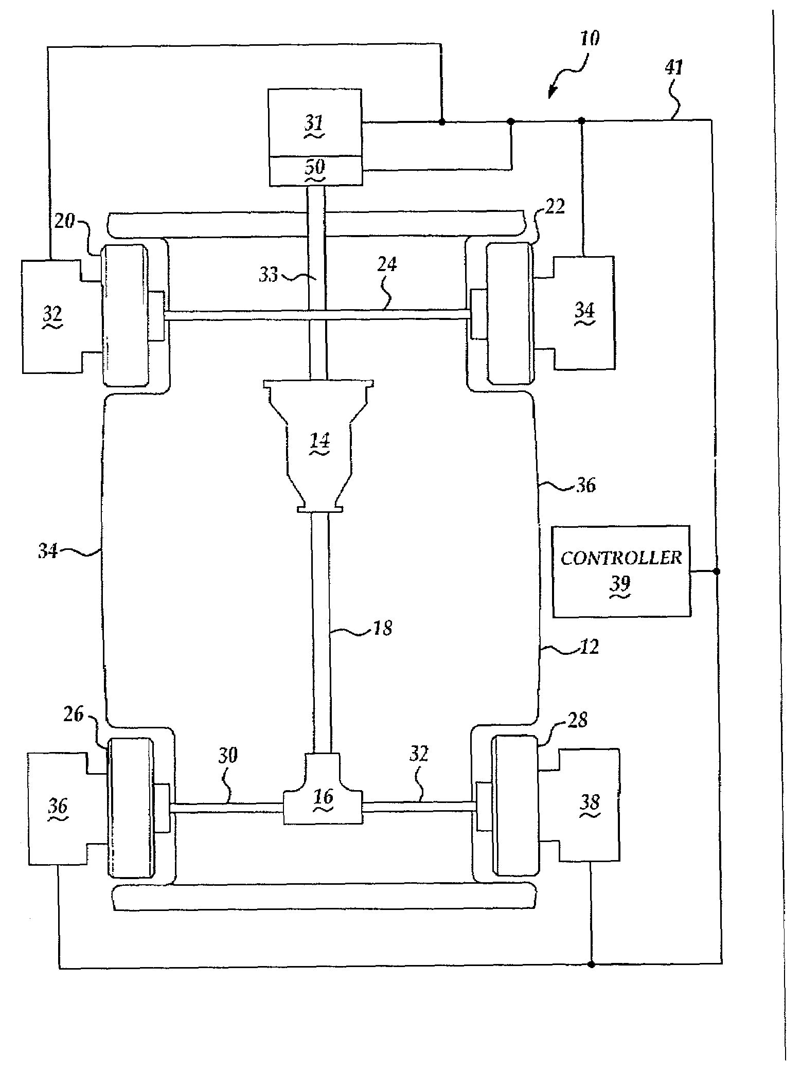
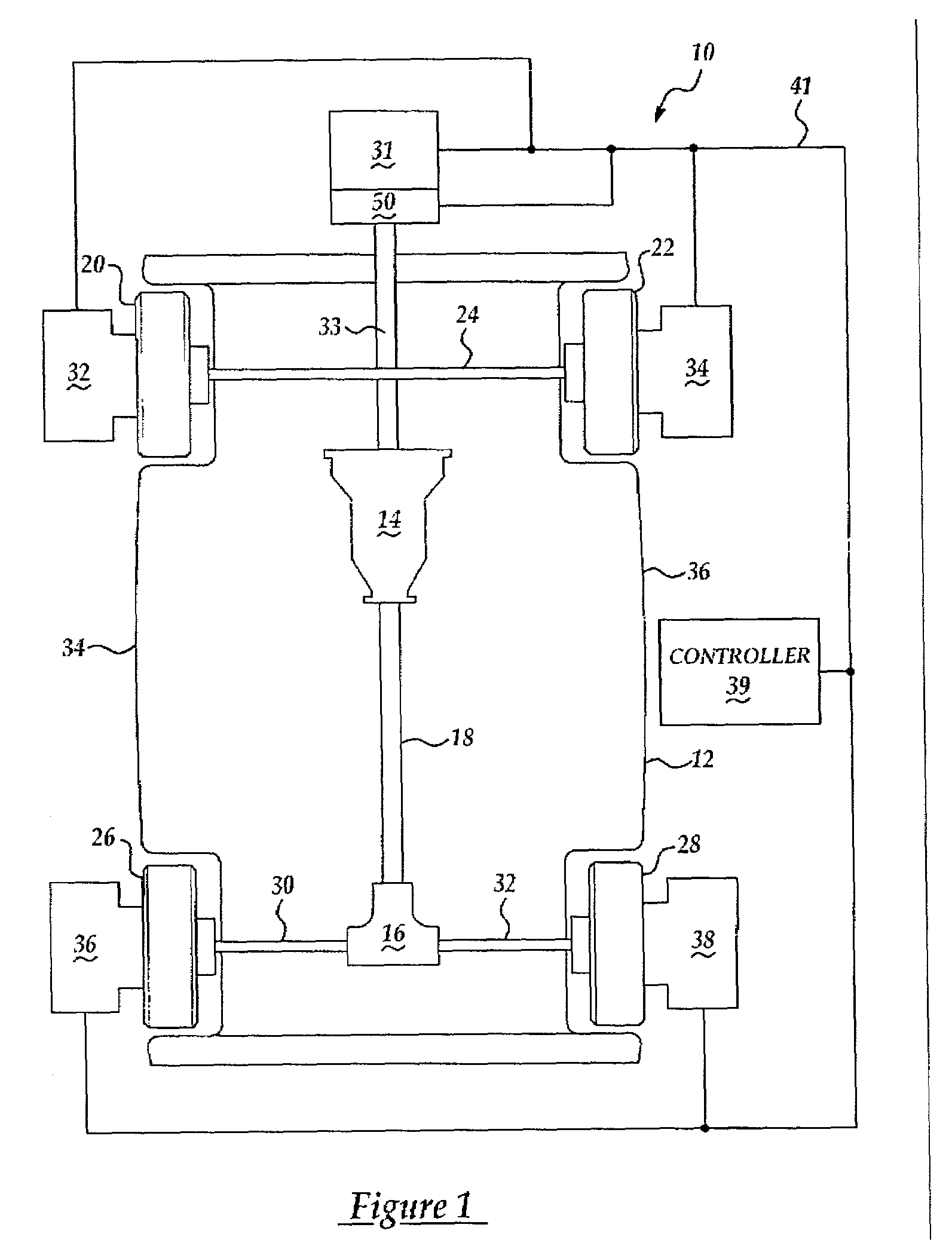
[0022]Referring now to FIG. 1, there is shown an apparatus 10 which is made in accordance with the teachings of the preferred embodiment of the invention in combination with a vehicle of the type having a transmission assembly 14, a differential assembly 16, a front axle 24, and a rear axles or “half shafts”30, 32. Particularly, the differential assembly 16 is coupled to the transmission assembly 14 by a drivetrain or driveshaft assembly 18. The vehicle 12 further includes front wheels 20, 22 which are coupled to the front axle 24, and rear wheels 26, 28 which are respectively coupled to the differential assembly 16 by axles or “half-shafts”30, 32. The vehicle further includes frame members 34, 36 which operatively receive axles 24, 30, and 32. It should be understood that while one type or configuration of vehicle is represented by the vehicle, other types of vehicles may be used in combination with the apparatus 10 and that nothing in this description is meant to limit the applica...


PUM


Abstract

An assembly 10 which allows a vehicular damper to be virtually created and evaluated. Particularly, the assembly 10 includes a torque producer 31, a frequency filter generator 50, and analyzers 32, 34, 36 and 38. The torque produce 31 selectively produces a torque signal which is combined with a selected frequency filter provided by the generator 50, thereby producing a dampened signal which is communicated to a transmission assembly 14. The analyzer detects noise and vibration and allows a designer to evaluate the chosen frequency filter. Other filters may be used and a filter is selected based upon the noise and vibration measurements made by the analyzers 32, 34, 36, and 38. An actual damper is then constructed having a frequency characteristic which is substantially similar to the frequency characteristic of the chosen frequency filter.

Description

BACKGROUND OF INVENTION[0001]1. Field of the Invention[0002]The present invention generally relates to a method and an apparatus for designing and developing a vehicular damper and more particularly, to a method and an apparatus for efficiently and accurately simulating the operation of a vehicular damper in a manner which obviates the need for tangibly or physically creating the damper while efficiently allowing various different damper designs or configurations to be accurately evaluated and modified.[0003]2. Background of the Invention[0004]A vehicular damper, such as a clutch or a torque converter, is typically coupled to a rotating member, such as a crankshaft, and to a transmission assembly. More particularly, the vehicular damper is adapted to selectively transfer the torque from the crankshaft to the coupled assembly in a manner which is effective to desirably reduce the amount of vibration, and noise, (e.g., hereinafter sometimes referred to as “VN”) which otherwise would b...

Claims


Application Information

Patent Timeline
IPC IPC(8): G06G7/48G01L3/26G01M15/00G06F19/00G01M17/00
CPCB60W40/00
Inventor ABE, TAKESHI
Owner FORD GLOBAL TECH LLC
Learn More