Turbine speed control system and method

a technology of turbine speed control and control method, which is applied in the direction of valve housing, machines/engines, transportation and packaging, etc., can solve the problems of high cost and reliability, difficult speed control, and complex proportional valves, so as to minimize system weight, improve efficiency, and optimize system performance

Active Publication Date: 2007-03-27
HONEYWELL INT INC
View PDF22 Cites 31 Cited by
  • Summary
  • Abstract
  • Description
  • Claims
  • Application Information

AI Technical Summary

Benefits of technology

[0009]One embodiment of the invention provides a novel turbine speed control method (TSCM) for an electric power generation system (EPGS) using a turbine as a prime mover. The control is based on on / off modulation of two valves, hydrogen and oxygen. The turbine control provides speed control and temperature control for optimized system performance and minimized system weight. Furthermore, the TSCM provides a compensation for speed droop due to delays in valve operation. A bang-bang speed control method with dynamic load dependent, speed droop compensation is implemented to solve this speed droop. Control thresholds for the turbine speed are adjusted based on load so as to compensate for increased overshoot at low load and the increased undershoot at high load. Such unique control method enhances the performance of any control system using discrete two-position control valves and is particularly valuable in vehicular and aerospace turbine power applications.

Problems solved by technology

This is particularly true in vehicle applications where the available energy is typically limited to that which the vehicle can carry.
Speed control is challenging in vehicle applications because the loads on the turbine are often highly variable.
However, proportional valves are much more complex, costly and less reliable than discrete 2-position valves, which are either open or closed.
Furthermore, the control systems for proportional valves are more complex, especially in bipropellant combustion systems where two separate flows must be metered not only to control turbine speed but also to maintain the proper mixture of propellants.
As a result there is more of a speed overshoot at low loads than at high turbine loads.
This low-speed undershoot and high-speed overshot results in a wider speed band than would be possible if the thresholds were adjusted for a constant overshoot and undershoot.
The wider speed band is undesirable in that it results in lower turbine power system performance.
This problem is typical in bang-bang control systems.

Method used


Image

  • Turbine speed control system and method
  • Turbine speed control system and method
  • Turbine speed control system and method

Examples


Embodiment Construction

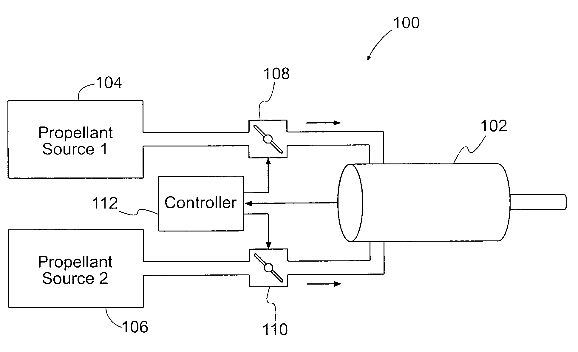
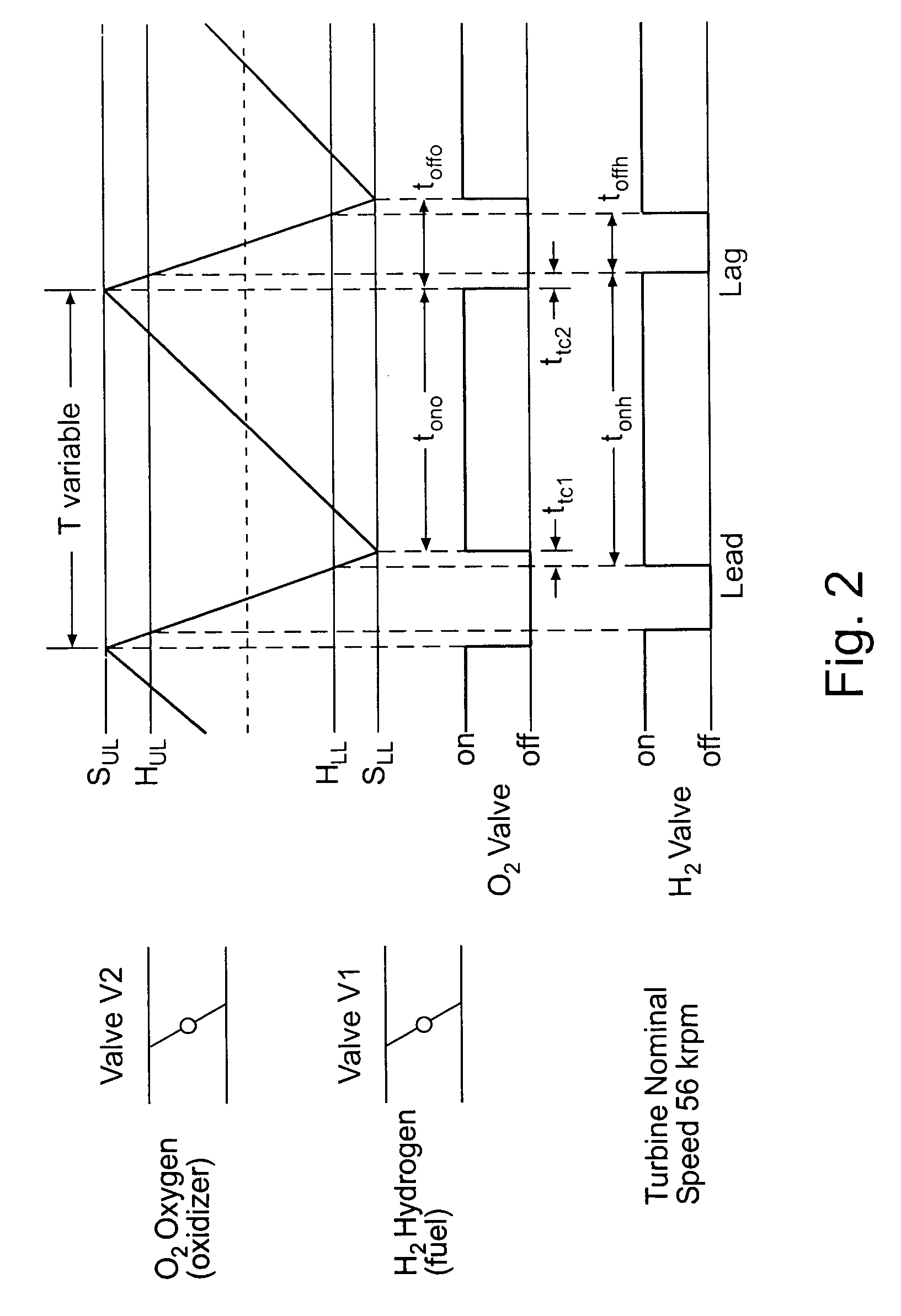
[0016]Devices and apparatus that implement the embodiments of the various features of the invention will now be described with reference to the drawings. The drawings and the associated descriptions are provided to illustrate embodiments of the invention and not to limit the scope of the invention. Reference in the specification to “one embodiment” or “an embodiment” is intended to indicate that a particular feature, structure, or characteristic described in connection with the embodiment is included in at least an embodiment of the invention. The appearances of the phrase “in one embodiment” or “an embodiment” in various places in the specification are not necessarily all referring to the same embodiment. Throughout the drawings, reference numbers are re-used to indicate correspondence between referenced elements. In addition, the first digit of each reference number indicates the figure in which the element first appears.

[0017]In the following description, certain terminology is u...


PUM


Abstract

One embodiment of the invention provides a turbine control system that adjusts the control thresholds of two-position valves, which provide propellant to the turbine, based on turbine load so as to compensate for increased turbine speed overshoot at low load and the increased turbine speed undershoot at high load. These two-position on-off modulated valves are used in a bang-bang (fully open or fully closed) regulation scheme to eliminate or minimize speed droop by using variable speed bounds implemented as a function of load.

Description

FIELD OF THE INVENTION[0001]Various embodiments of the invention pertain to power generation systems. More particularly, one embodiment of the invention pertains to a method and system for turbine speed control for a turbine-driven electric power generation system.DESCRIPTION OF RELATED ART[0002]Turbines are often used to generate power for both stationary and vehicle applications. They are usually driven by hot, compressed gas and are used to produce shaft, hydraulic, pneumatic or electric power. The energy to produce the hot gas may come from any of a number of sources.[0003]Turbines are typically designed with an optimum rotational speed at which they provide optimum performance. Optimum performance refers to the maximum output power achieved for a given input of energy. Similarly, the devices driven by such turbines have optimum, and hopefully similarly matched, design speeds. In applications where the amount of input energy is limited, it is often desirable to maintain the turb...

Claims


Application Information

Patent Timeline
Patent Type & Authority Patents(United States)
IPC IPC(8): F02C9/16F02C9/26
CPCF02C9/28Y02T50/671Y02T50/60Y10T137/87314
Inventor GANEV, EVGENIKOERNER, MIKE S.LIU, CHUNG Y.
Owner HONEYWELL INT INC
Why Eureka
Try Eureka