Laser scanning unit

Inactive Publication Date: 2007-03-27
S PRINTING SOLUTION CO LTD
View PDF27 Cites 16 Cited by
  • Summary
  • Abstract
  • Description
  • Claims
  • Application Information

AI Technical Summary

Benefits of technology

[0011]It is another object of the present invention to provide a laser scanning unit having a sim

Problems solved by technology

However, the conventional laser scanning unit constructed as above has the following problems.
First, in order to obtain a quality image, the structure of the f-θ lens 15 is complicated, making the unit l

Method used


Image

  • Laser scanning unit
  • Laser scanning unit
  • Laser scanning unit

Examples


Embodiment Construction

[0032]Reference will now be made in detail to the present preferred embodiments of the present invention, examples of which are illustrated in the accompanying drawings, wherein like reference numerals refer to like elements throughout.

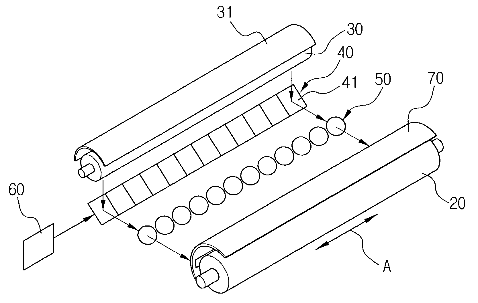
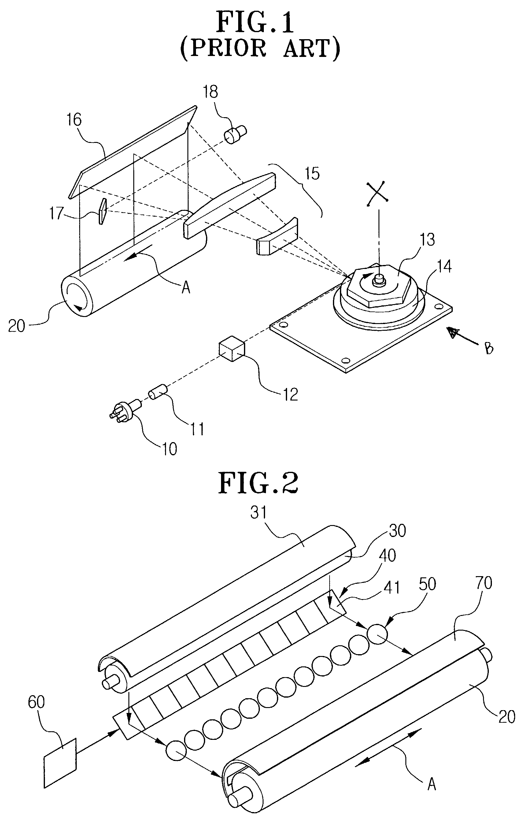
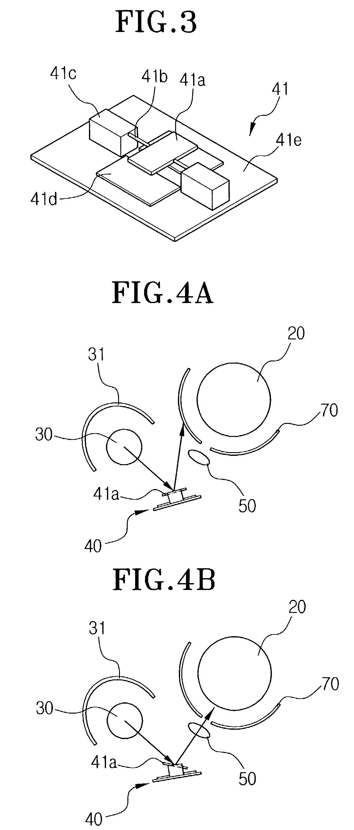
[0033]Referring to FIG. 2, the laser scanning unit according to an embodiment of the present invention includes a light source 30 to generate light, a reflective member 31 to collect the light generated from the light source 30 in a predetermined direction, and a micro-mirror array 40 to reflect the light collected by the reflective member 31 toward the photosensitive medium, i.e., toward the photosensitive drum 20. The present laser scanning unit also includes a driving control unit 60 to drive the micro-mirror array 40, and a micro-lens array 50 to focus the light reflected from the micro-mirror array 40 on the photosensitive drum 20.

[0034]The light source 30 has a predetermined length, and a cylindrical shape, and may be a fluorescent light or a ha...


PUM


Abstract

A laser scanning unit to form an electrostatic latent image according to an image signal by projecting a light onto a photosensitive medium. The laser scanning unit has a light source having a cylindrical shape of a predetermined length; a reflective member surrounding the light source to focus the light from the light source; a micro-mirror array to reflect the light focused by the reflective member toward the photosensitive medium; a driving control unit to drive the micro-mirror array according to the image signal; and a micro-lens array disposed in an optical path between the micro-mirror array and the photosensitive medium, to focus the light reflected from the micro-mirror array onto the surface of the photosensitive medium.

Description

CROSS-REFERENCE TO RELATED APPLICATIONS[0001]This application claims the benefit of Korean Application No. 2001-63694, filed Oct. 16, 2001, in the Korean Industrial Property Office, the disclosure of which is incorporated herein by reference.BACKGROUND OF THE INVENTION[0002]1. Field of the Invention[0003]The present invention relates to a laser scanning unit, and more particularly, to a laser scanning unit to improve speed and compactness of a laser printer.[0004]2. Description of the Related Art[0005]Generally, a laser printer reproduces an image by focusing a laser beam from a laser diode onto a photosensitive drum 20 (see FIG. 1) with respect to an image signal, and transferring an electrostatic latent image from the photosensitive drum 20 to a printing medium such as paper. Such a laser printer has a scanning unit to generate and focus the laser beam onto the photosensitive drum 20.[0006]FIG. 1 is a schematic view showing the structure of a conventional laser scanning unit. Refe...

Claims


Application Information

Patent Timeline
IPC IPC(8): G06K7/10B41J2/445B41J2/465G03G15/04
CPCB41J2/471B41J2/465G03G15/04
Inventor YOO, JAE-HWAN
Owner S PRINTING SOLUTION CO LTD
Why Eureka
Try Eureka