Francis turbine

a turbine and turbine blade technology, applied in the field of turbine blades, can solve problems such as loss of hydraulic efficiency, and achieve the effects of reducing a circumferential velocity component, improving the shape of blades, and reducing secondary flow

Inactive Publication Date: 2007-03-27
KK TOSHIBA
View PDF10 Cites 8 Cited by
  • Summary
  • Abstract
  • Description
  • Claims
  • Application Information

AI Technical Summary

Benefits of technology

[0010]Accordingly, an advantage of an aspect of the present invention is to provide a Francis turbine with an improved shape of blades that can reduce a circumferential velocity component generated in the flow downstream of the blades in a condition of a partial load operation, or reduce the secondary flow around the blades.

Problems solved by technology

Especially, it is known that secondary flow, which is a flow not being along a flow line, distorts a pressure distribution on the blades and results in loss of hydraulic efficiency.

Method used


Image

  • Francis turbine
  • Francis turbine
  • Francis turbine

Examples


first embodiment

[0022]A first embodiment in accordance with the present invention will be explained with reference to FIGS. 1 to 3.

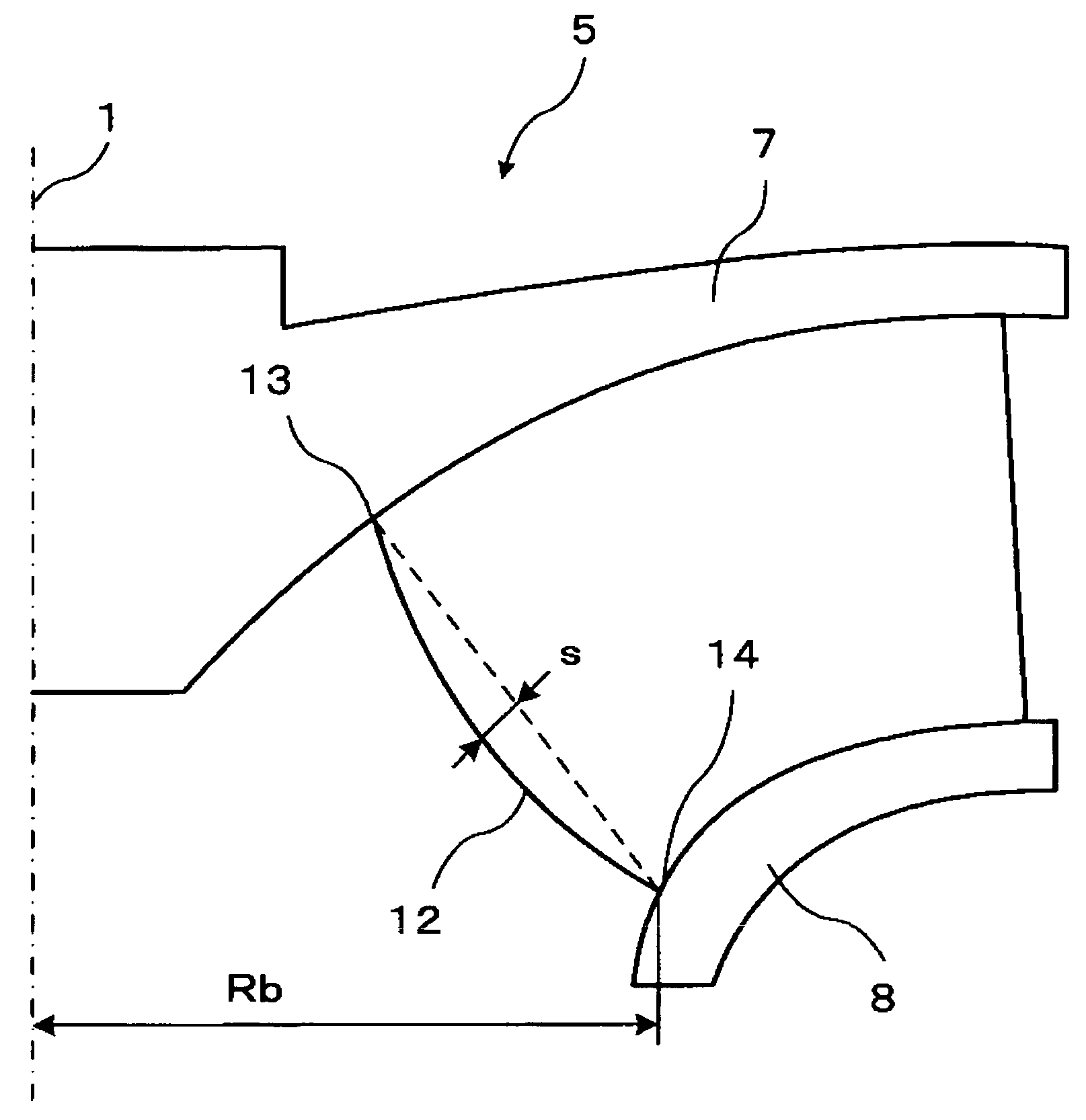
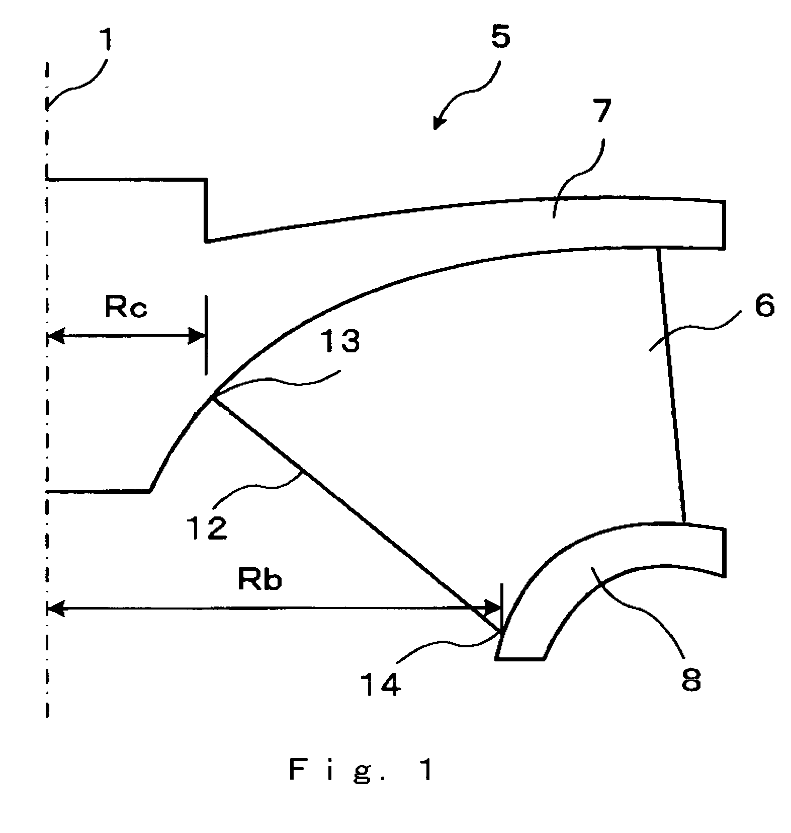
[0023]FIG. 1 is a half cross sectional view including a center axis of a Francis turbine runner according to the first embodiment. Since the Francis turbine runner rotates around the center axis (also referred to as a rotation axis), half of the drawing is omitted as it has a symmetric profile in FIG. 1.

[0024]As shown in FIG. 1, a Francis turbine runner 5 includes a crown 7, a band 8, and a plurality of runner blades 6. Crown 7 is connected to a rotating shaft (not shown) at a rotation axis 1. Runner blades 6 are circumferentially arranged on the crown 7. In FIG. 1, one of runner blades 6 is shown as a projected profile on a meridian plane, which is a plane including the rotation axis 1. Band 8 is connected to runner blades 6 and is arranged so that the rotation axis 1 becomes in the center. Thus, band 8 is coaxially coupled with the crown 7 by the runner blades 6. In o...

second embodiment

[0038]A second embodiment in accordance with the present invention will be explained with reference to FIGS. 4 to 6.

[0039]FIG. 4 is a half cross sectional view including a center axis of a Francis turbine runner according to the second embodiment. Since the Francis turbine runner rotates around the center axis (also referred to as a rotation axis), half of the drawing is omitted as it has a symmetric profile in FIG. 4. The same symbols are used for the same elements shown in FIG. 1 and detailed description of those elements is omitted.

[0040]As shown in FIG. 4, a Francis turbine runner 5 includes a crown 7, a band 8, and a plurality of runner blades 6. Crown 7 is connected to a rotating shaft (not shown) at a rotation axis 1. Runner blades 6 are circumferentially arranged on the crown 7. Band 8 is connected to runner blades 6 and is arranged so that the rotation axis 1 becomes in the center. Thus, band 8 is coaxially coupled with the crown 7 by the runner blades 6. Same as FIG. 1, th...


PUM


Abstract

A Francis turbine with an improved shape of blades, which can reduce a circumferential velocity component generated in the flow downstream of the blades in a condition of a partial load operation, or reduce the secondary flow around the blades, is provided. A Francis turbine comprises a crown, a plurality of blades, and a band. The crown can rotate around a rotating axis. The blades are circumferentially arranged on the crown, each of which including an inner end as a trailing edge. The band is coaxially coupled with the crown by the blades. A distance Rc can be defined as a distance between the rotation axis and an end by the crown side of the trailing edge. A distance Rb can be defined as a distance between the rotation axis and an end by the band side of the trailing edge. The distance Rc and the distance Rb satisfy0.2≤RcRb≤0.4.

Description

CROSS REFERENCE TO RELATED APPLICATION[0001]This application is based upon and claims the benefit of priority from prior Japanese Patent Application No. 2003-291266 filed on Aug. 11, 2003, the entire contents of which are incorporated herein by reference.FIELD OF THE INVENTION[0002]This invention relates to a Francis turbine that is used for a hydraulic turbine or a pump, and in particular, a Francis turbine having blades with an improved shape on a trailing edge.BACKGROUND[0003]A Francis turbine is used in a hydraulic machine, including a reversible pump-turbine, for power generation.[0004]A conventional Francis turbine runner is described in U.S. Pat. No. 4,479,757. This conventional Francis turbine runner includes blades whose inlet (a leading edge) shape is curved toward a direction opposite to a rotating direction of a turbine operation from a band side to a crown side.[0005]Another conventional Francis turbine runner is described in U.S. Pat. No. 6,135,716. This conventional F...

Claims


Application Information

Patent Timeline
Patent Type & Authority Patents(United States)
IPC IPC(8): F03B3/02F03B3/12F01D17/12F03B3/10
CPCF03B3/125Y10S416/02Y02E10/223Y02E10/20
Inventor ENOMOTO, YASUYUKISUZUKI, TOSHIAKIKUROSAWA, SADAONAKAMURA, TAKANORI
Owner KK TOSHIBA
Why Eureka
Try Eureka