Eureka AIR delivers breakthrough ideas for toughest innovation challenges, trusted by R&D personnel around the world.

Heat dissipation assembly and method for producing the same

a technology of heat dissipation assembly and heat dissipation rate, which is applied in the direction of solid-state devices, basic electric elements, chemistry apparatus and processes, etc., can solve the problems of incompatible relationship between the two methods for reducing thermal resistance described above, inability to reduce thermal resistance due to making the sheet b>4/b> flexible, and may lose elasticity, so as to achieve effective reduction of thermal resistance and prevent the effect of conducting sh

Active Publication Date: 2007-03-27
NISSAN MOTOR CO LTD +2
View PDF5 Cites 12 Cited by
  • Summary
  • Abstract
  • Description
  • Claims
  • Application Information

AI Technical Summary

Benefits of technology

[0016]The present invention has as an object to solve the problems described above. More particularly, the present invention has as an object to provide a heat dissipation assembly which can effectively dissipate heat from a heat generator such as a semiconductor device or the like, while electrically insulating properties are maintained for a long period of time.
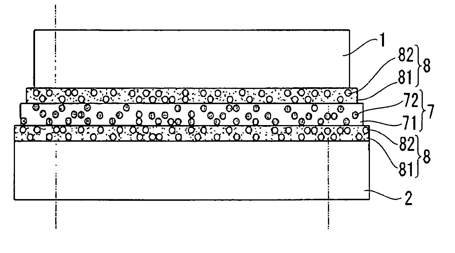
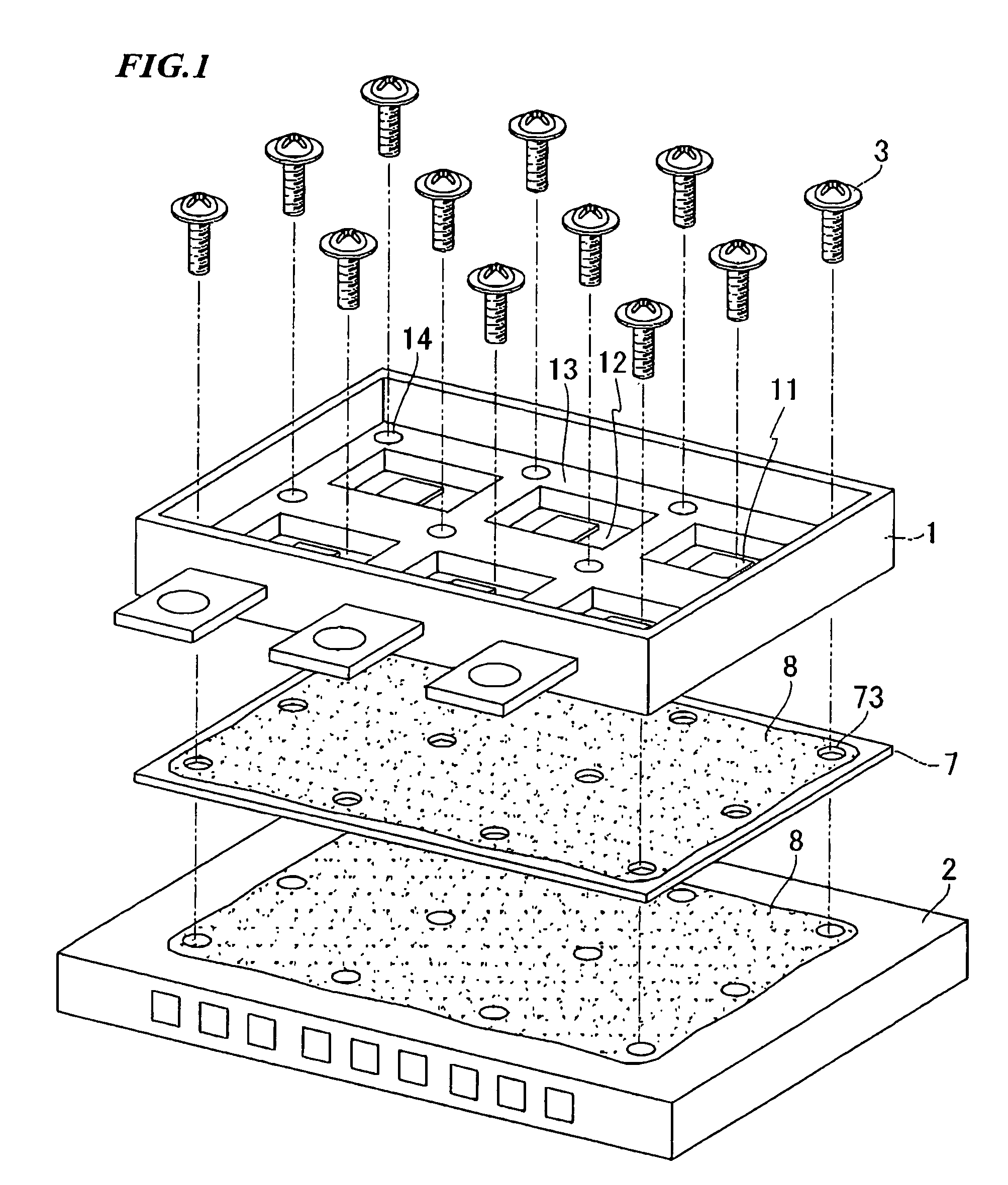
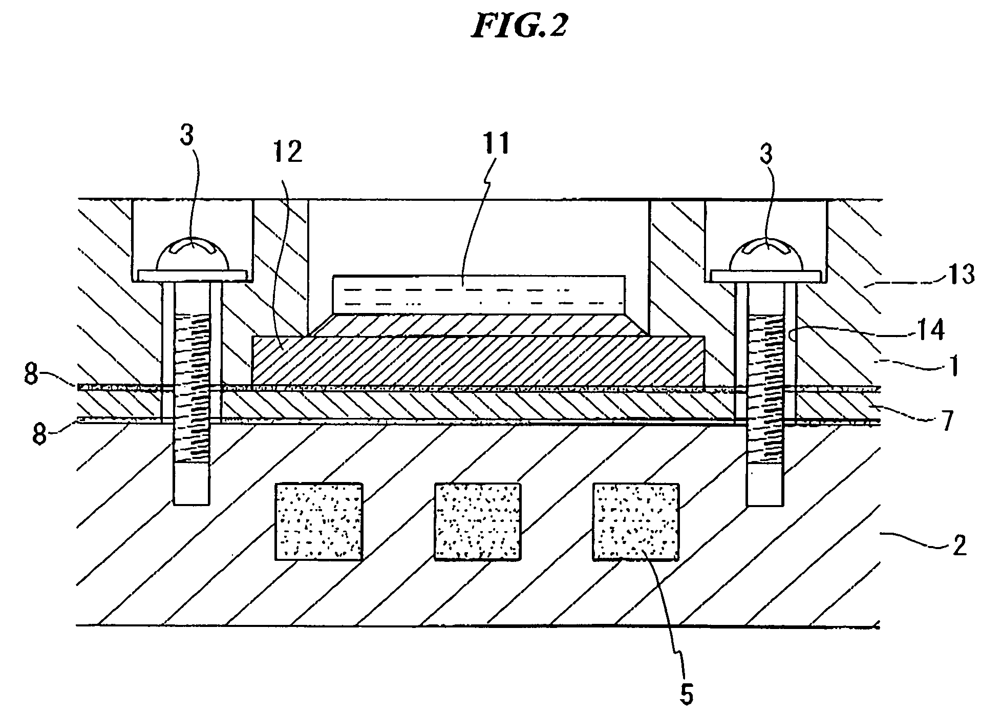
[0032]According to the heat dissipation assembly of the present invention, even if plural heat cycles are applied, occurrences of cracks in the electrically insulating and heat; conductible sheet can be prevented. Therefore, heat from the heat generator such as a semiconductor device or the like can be effectively dissipated while electrically insulating properties are maintained, over a long period of time. In addition, since a thermally conductive grease is filled in the microirregularities on the surfaces of the heat generator and the heat dissipator, thermal resistance can be effectively reduced, and a high heat dissipation rate can be exhibited. In particular, in the case of employing a specific combination of base materials of the thermally conductive grease and the electrically insulating and thermally conductive sheet, the effects described above are prominently exhibited.
[0033]In addition, according to the heat dissipation assembly of the present invention, even if the thermally conductive grease and / or the electrically insulating and thermally conductive sheet described above include a thermally conductive filler as a solid content, electrical insulation can be maintained over a long period of time, and effective heat dissipation can be carried out. In particular, in the case in which the thermally conductive filler is a mixture of fillers having different particle sizes, the charging rate of the thermally conductive filler can be increased. In addition, in the case in which the filler is contained in the thermally conductive grease, the charging rate can be increased while the consistency of the grease described above is well maintained, and for this reason, the heat dissipation efficiency can be further improved.
[0034]In the method for producing a heat dissipation assembly of the present invention, the heat dissipation assembly described above can be effectively produced. In particular, a thermally conductive grease can be thinly spread, and for this reason, in particular, the application operation can be effectively carried out, and thermal resistance can be further reduced. In addition, in the press-bonding step described above, the thermally conductive grease can be spread, and for this reason, bubbles in the grease can be removed, and heat dissipation efficiency can thereby be increased.

Problems solved by technology

However, the two methods for reducing thermal resistance described above are in an incompatible relationship.
For this reason, reducing thermal resistance due to making the sheet 4 flexible is limited.
However, in practice, when the sheet 4 in which the grease 6 is applied to the surfaces thereof is used for a long period of time under increased temperatures such as the temperatures during operating the semiconductor elements, the grease 6 is denatured and is solidified, and the sheet 4 may lose elasticity, and finally, the electrically insulating properties of the sheet 4 are lost.
Therefore, there is a problem in that insulating defects of the semiconductor device 1 (electrode plates 12) occur.
As a result, between the semiconductor device 1 and the metallic heat sink 2, insulating defects occur.

Method used


Image

  • Heat dissipation assembly and method for producing the same
  • Heat dissipation assembly and method for producing the same
  • Heat dissipation assembly and method for producing the same

Examples


embodiment 1

[0105]To a base in which 5 parts by weight of dry silica (silicon dioxide powder, Nippon Aerosil Co., Ltd., product name: Aerosil 200) as a reinforcing filler was mixed and kneaded with 100 parts by weight of methylvinylsilicone raw rubber, 700 parts by weight of aluminum oxide (produced by Showa Denko Co., Ltd., product name AL-30) was added as a thermally conductive filler, thus producing a compound. Subsequently, a curing agent comprising 50% bis-2,4-dichlorobenzoyl peroxide was added, as a curing agent, in an amount of 5 parts by weight with respect to 100 parts by weight of the methylvinylsilicone raw rubber in the compound, and was uniformly dispersed and mixed, thus producing a compsition. Subsequently, the composition was subjected to primary curing for 5 minutes at 120° C. using a thermovulcanizing press, and was subsequently subjected to secondary curing for 4 hours at 200° C. in a hot air oven, thus producing a silicone rubber sheet having a thickness of 0.20 mm.

[0106]On ...


PUM

PropertyMeasurementUnit
particle sizeaaaaaaaaaa
temperatureaaaaaaaaaa
thicknessaaaaaaaaaa

Abstract

A heat dissipation assembly in which a heat generator and a heat dissipator are integrated via an electrically insulating and thermally conductive sheet, at least one surface of which a thermally conductive grease is applied to, in which the thermally conductive grease is incompatible with the electrically insulating and thermally conductive sheet. Heat from the heat generator such as a semiconductor device or the like can be effectively dissipated while an electrically insulating condition is maintained over a long period of time.

Description

RELATED APPLICATIONS[0001]This application claims the benefit of Japanese Patent Application No. 2004-059140 filed on Mar. 3, 2004, the contents of which are herein incorporated by reference in their entirety.BACKGROUND OF THE INVENTION[0002]1. Field of the Invention[0003]The present invention relates to a heat dissipation assembly and a method for producing the same. In particular, the present invention relates to a heat dissipation assembly and a method for producing the same, in which heat from a heat generator such as a semiconductor device or the like is effectively dissipated while an electrically insulating condition is maintained, and superior durability for usage for a long period of time is exhibited.[0004]2. Description of Related Art[0005]Heretofore, various heat dissipation assemblies for cooling a heat generator such as a semiconductor device or the like have been proposed. FIG. 7 and FIG. 8 show one embodiment of a conventional heat dissipation assembly in a semicondu...

Claims


Application Information

Patent Timeline
Patent Type & Authority Patents(United States)
IPC IPC(8): H01L23/10H01L23/34H05K7/20C09K5/14H01L21/48H01L23/36H01L23/373H01L25/07
CPCC09K5/14H01L23/3735H01L23/3737H01L24/29H01L24/32H01L2224/32013H01L25/072
Inventor SHIBUYA, AKIHIROFURUKAWA, MOTOYUKINARUSE, MIKIOEHIRA, ATSUSHIOGAWA, KAZUHIROOOTA, HIROTOSHIABE, KAZUYOSHIIKEZAWA, ATSUSHIKAKEHI, TORU
Owner NISSAN MOTOR CO LTD
Why Eureka
Eureka Blog
Learn More