[0005]Referring to FIGS. 6 and 7, a prior art ceiling fan structure 80 includes a DC brushless motor 81 disposed inside a ceiling fan casing for driving the vanes 82 to produce airflows, wherein the brushless
DC motor 81 comprises a
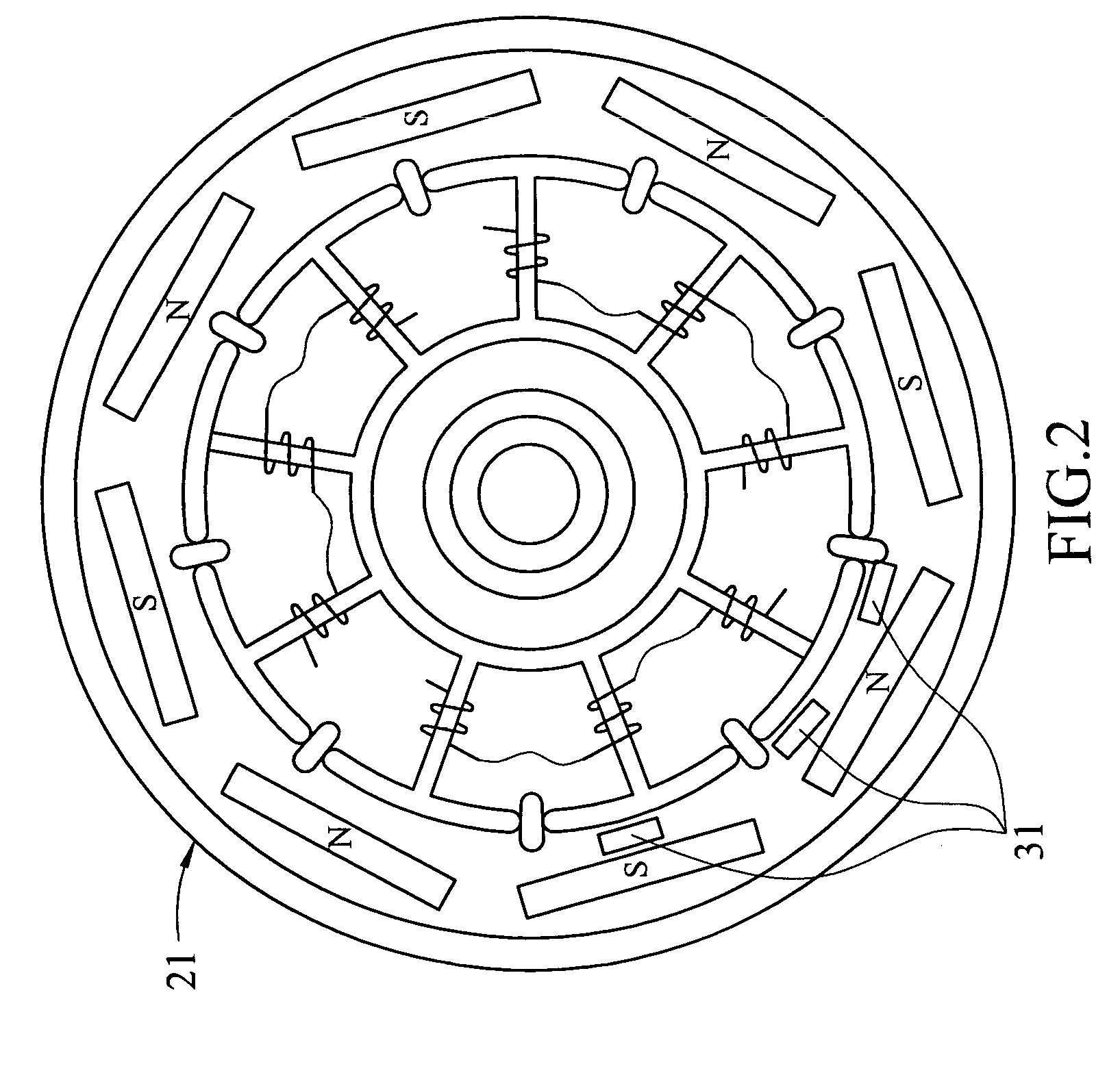
stator 83 and a rotor 84, and the rotor 84 includes a plurality of mutually repelled permanent magnets disposed in a circular yoke, characterized in that the
stator 83 includes a multi-polar
magnetism of more than two poles, and each
magnet includes a coil wound around the
magnet and Hall components 85, 86 on the sensing surface of a specific
magnet. The Hall components 85, 86 are coupled to an
electronic switch module 87, and each switch module of the
electronic switch module 87 is coupled to the power supply and each
electromagnetic coil, and the Hall components 85, 86 are used for detecting the polarity change of the permanent magnet, such that the corresponding electromagnetic activation drives the rotor to rotate, and the coil is electrically connected, and the best angle for the electromagnetic polarity is changed when the coil is electrically connected, so as to improve the motor performance.
[0006]Referring to FIG. 8 for another ceiling fan driving control device, a
remote control coder 90 is used for a ceiling fan that comprises a
microprocessor 91, a high-frequency
receiver 92, and an external memory (
EEPROM) 93, wherein the microprocessor 91 is connected to a power supply 94 for supplying power, and I / O contact points of the microprocessor 91 are coupled to a lamp 95 and a fan motor 96 respectively. Further, other I / O contact points of the microprocessor 91 are connected to a high-frequency
receiver 92 and an external memory 93, wherein the external memory 93 has the function of reading and writing memory in a power failure and can be used for automatically detecting and setting up the decoded address of the corresponding
transmitter by a RF coding function after the ceiling fan is powered on, so as to facilitate users to change the decoded address of the ceiling fan
remote control coder 90 and improve the inconvenient prior art that requires removing the whole ceiling fan before operating the switch address code of a
remote control device. Such ceiling fan driving control device provides a remote control coder that can avoid interferences and change the corresponding decoding address of remote control coder. However, such structure only provides a function of transmitting signals to drive the lamps 95 and ceiling fan motor 96, so as to achieve the function of the stepless speed adjusting function.
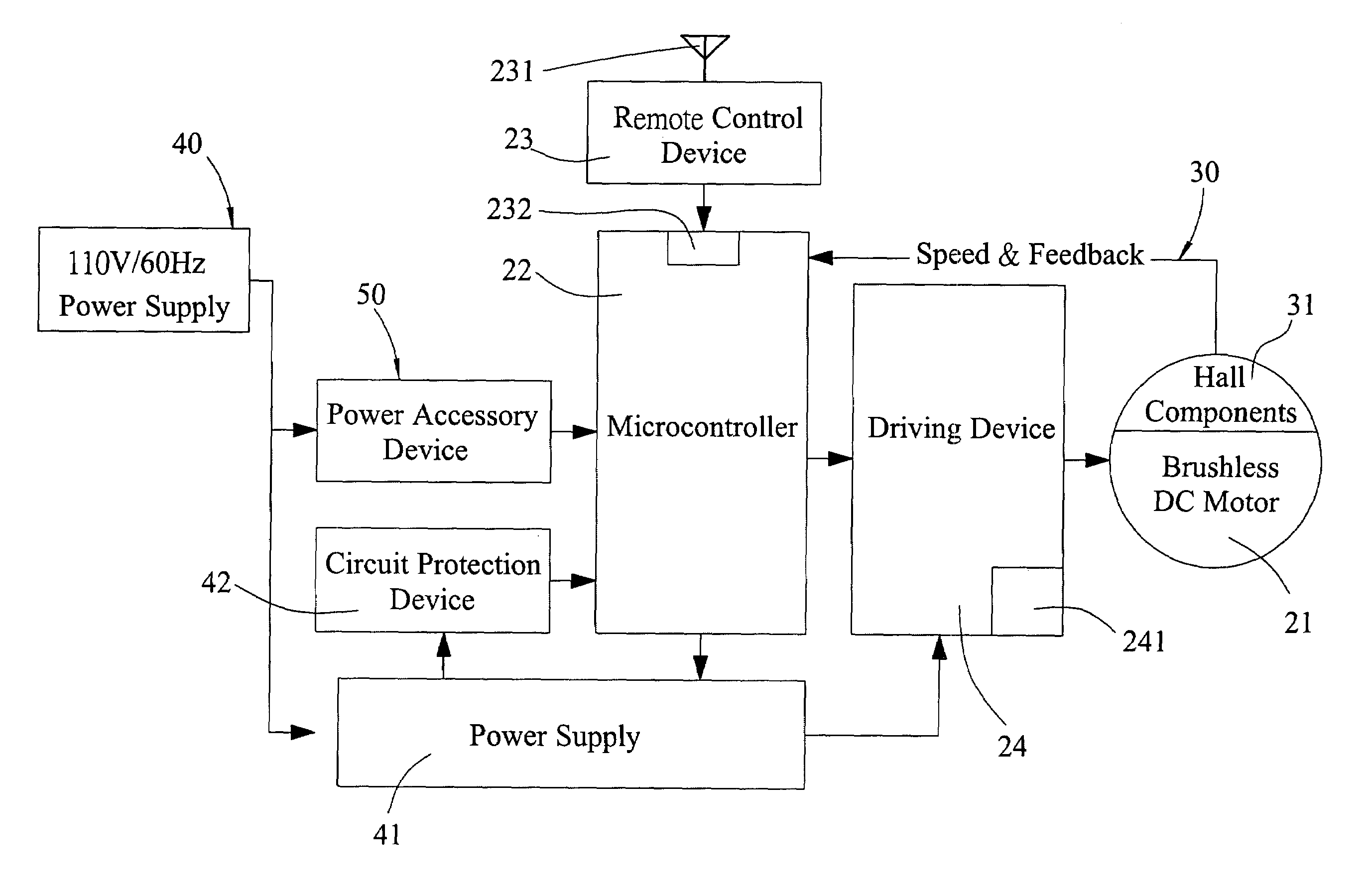
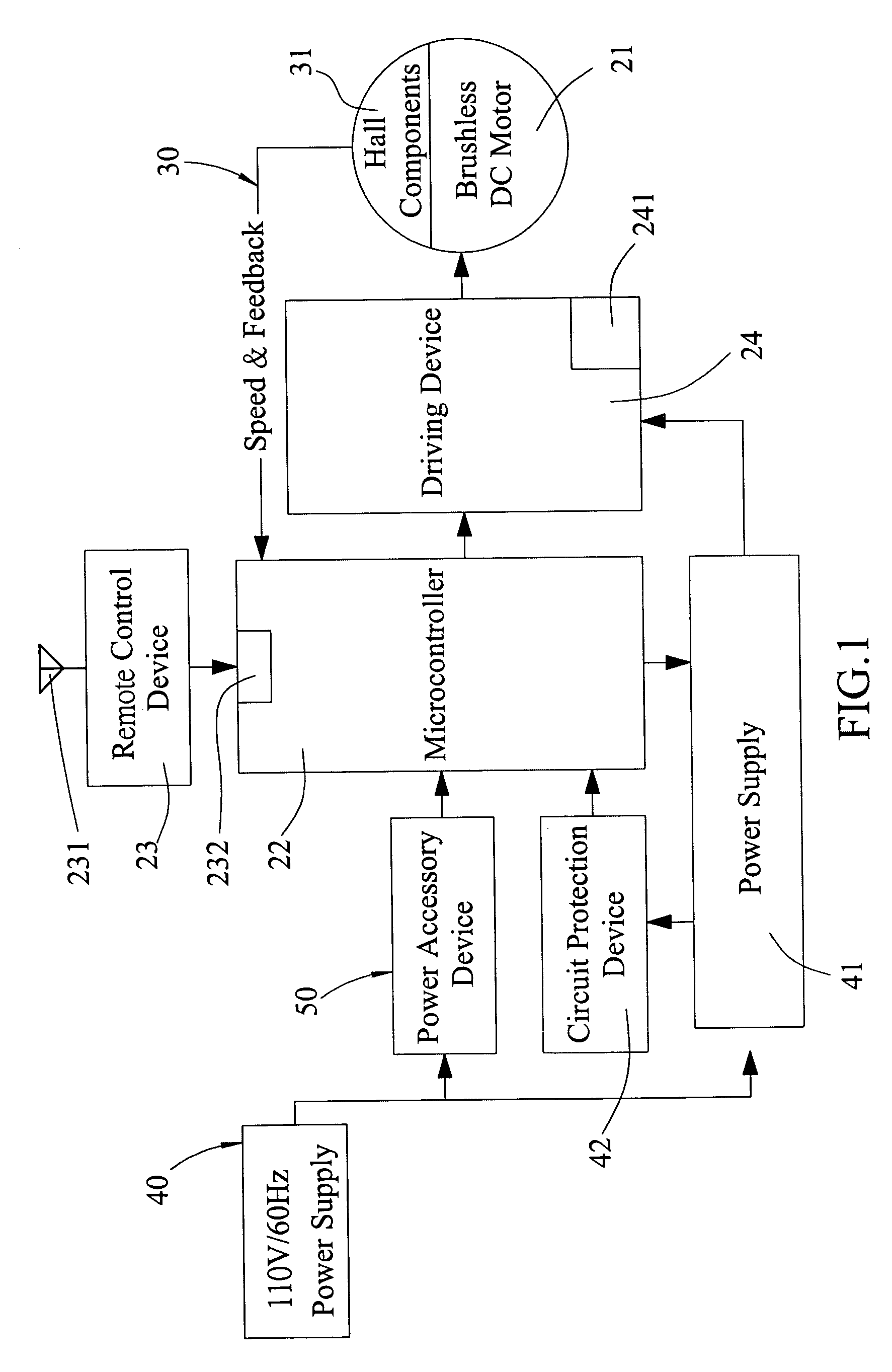
[0008]To overcome the foregoing shortcomings, the present invention discloses a universal low-power ceiling fan controller installed inside a ceiling fan casing, which comprises a brushless
DC motor installed in the ceiling fan casing, a microcontroller coupled to a power source and operating with a remote control device including a
transmitter and a receiver for sending data signals to the microcontroller by a
wireless transmission method, a driving device installed between the microcontroller and the brushless DC motor for turning on or off the ceiling fan, and a feedback device having at least three Hall components for continuously sensing a position variation and feeding back the position variation to the microcontroller to determine the speed of the brushless DC motor. With the foregoing components, the microcontroller receives a
signal from the remote control device, and the driving device drives the brushless DC motor to rotate by means of a sample
signal feedback of the feedback device for the microcontroller to determine and conduct an automatic compensation, so as to maintain a constant rotary speed of the vanes of the ceiling fan while reducing the
power consumption.
[0012]Another further objective of the present invention is to provide a universal low-power ceiling fan controller applicable for ceiling fans with a brushless DC motor, so as to greatly reduce the
power consumption and maximize the
power saving effect.

