NMR MAS electret spin rate detection

a technology of mas electret and spin rate detection, which is applied in the direction of magnetic measurements, instruments, measurement devices, etc., can solve the problems of low phase stability, low signal strength at the fundamental frequency of a well-balanced rotor, and low phase stability of the detection, so as to achieve high sensitivity and phase stability in the detection of spin rate, and simple antenna

Inactive Publication Date: 2007-03-27
DOTY SCI
View PDF13 Cites 27 Cited by
  • Summary
  • Abstract
  • Description
  • Claims
  • Application Information

AI Technical Summary

Benefits of technology

[0014]A material having a permanent external diametrical electric field is included within an NMR MAS spinner. Such materials include ferroelectret porous films, in which the electric polarization arises from opposite mono-polar charges on separated surfaces within a structured material containing voids. Rotation of electrically polarized material produces a time-dependent electric field, modulated at the rotational frequency, so that a simple antenna achieves high sensitivity and phase stability in spin rate detection. The electrically polarized material is also of sufficiently high resistivity that modulation of the external NMR polarizing magnetic field B0 is negligible.

Problems solved by technology

The problem with this method is that the acoustic signal strength at the fundamental frequency from a well-balanced rotor is generally too low for adequate phase stability of the detection, even with sophisticated filtering.
Of course, relying on a random process makes phase accuracy impossible, and the signal strength often drops below the noise level.
Also, the harmonic content of the signal is unpredictable.
Still, this method is often used, as it is simple to implement, while the optical method is not always as easy to implement as one might suppose.
The challenges of implementing optical spin rate detection arise predominately from the fact that space is extremely precious near the spinning sample, as every bit is needed to optimize both the rf coils and the spinner system.
Small light pipes are fragile, and it has often been difficult to achieve adequate S / N in the optical signal for the desired phase accuracy.

Method used


Image

  • NMR MAS electret spin rate detection
  • NMR MAS electret spin rate detection
  • NMR MAS electret spin rate detection

Examples


Embodiment Construction

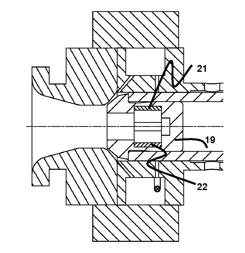
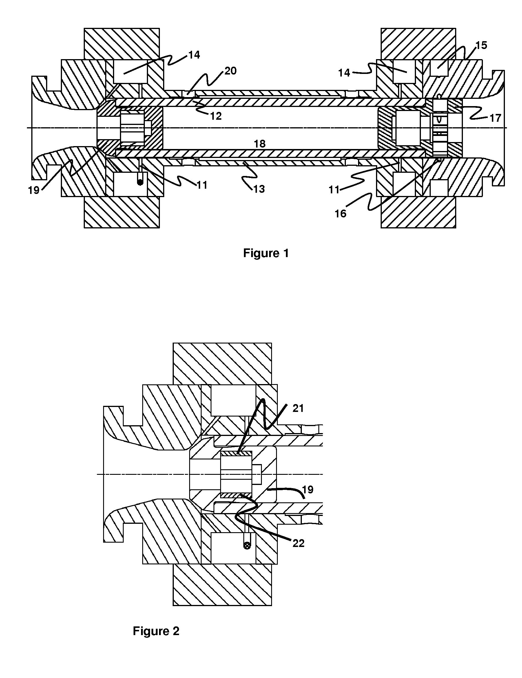
[0018]The representative high-speed NMR sample spinner shown in FIG. 1 is disclosed in more detail in the above-mentioned co-pending application Ser. No. 11 / 163,344. It has hydrostatic air radial bearing orifices 11 introducing pressurized gas radially to support the ceramic rotor 12 near both ends inside the ceramic cylindrical stator 13, according to the prior art. Bearing manifolds 14 are provided for distribution of air to the radial bearing orifices, and a drive manifold 15 is provided for distribution of air to the tangentially directed drive nozzles 16, which enable the microturbine 17 at the “top” or “front” of the rotor to spin the rotor 12 and its NMR sample 18. The axial bearing tip 19 is pressed into the “bottom” or “rear” of the rotor. Central bearing exhaust holes 20 are provided at axial locations somewhat closer to the middle of the stator than the bearing orifices, in regions where the cylindrical stator inside diameter is greater than in the immediate vicinity of t...


PUM


Abstract

A material having a permanent external diametrical electric field is included within an NMR MAS spinner. Such materials include ferroelectret porous films, in which the electric polarization arises from opposite mono-polar charges on separated surfaces within a structured material containing voids. Rotation of electrically polarized material produces a time-dependent electric field, modulated at the rotational frequency, so that a simple antenna achieves high sensitivity and phase stability in spin rate detection. The electrically polarized material is also of sufficiently high resistivity that modulation of the external NMR polarizing magnetic field B0 is negligible.

Description

CROSS-REFERENCE TO RELATED APPLICATIONS[0001]This application claims priority from U.S. application No. 60 / 594,326, filed Mar. 29, 2005, which application is hereby incorporated herein by reference for all purposes.FIELD OF THE INVENTION[0002]The field of this invention is high-speed cylindrical sample spinners for Nuclear Magnetic Resonance (NMR) Magic Angle Spinning (MAS).BACKGROUND OF THE INVENTION[0003]A large number of techniques have been developed to improve the spectral resolution in Nuclear Magnetic Resonance (NMR) of solid samples, and most modern techniques include extremely rapid spinning (10–30 kHz) of the sample at the “Magic Angle” (the zero of the second Legendre polynomial, 54.7°) with respect to B0. If the rotational rate is fast compared to chemical shift anisotropies and dipolar couplings (in units of Hz), the resolution is dramatically improved—often by two or three orders of magnitude. Even when the spinning is not fast enough to satisfy the above conditions, s...

Claims


Application Information

Patent Timeline
Patent Type & Authority Patents(United States)
IPC IPC(8): G01V3/00
CPCG01R33/307
Inventor DOTY, F DAVID
Owner DOTY SCI
Why Eureka
Try Eureka