Imaging apparatus and method

a technology of imaging apparatus and sar image, applied in the field of synthetic aperture imaging apparatus, can solve the problems of inconvenient data storage, inconvenient operation, and high computational cost, and achieve the effects of reasonable data storage requirement, reasonable cost, and feasible

Inactive Publication Date: 2007-03-27
ASTRIUM GMBH
View PDF14 Cites 31 Cited by
  • Summary
  • Abstract
  • Description
  • Claims
  • Application Information

AI Technical Summary

Benefits of technology

[0015]It is the principal object of the present invention to provide a low cost radar imaging apparatus which is reliable for application as an attitude sensor. This is achieved by elimination of inertial / geocentric attitude sensors from the inventive design.
[0026]It is to be appreciated that the imaging apparatus and method of the invention can be implemented at reasonable cost, and that it has utility for various applications, for example in space-borne radar missions and air-borne radar missions. The present invention is advantageously applicable to any radar waveband.
[0027]It is also to be appreciated that the present invention can be conveniently used to establish spacecraft pointing about two reference axes with feasible computational effort, a reasonable data storage requirement and with sufficient precision to ensure that reliable data are collected by the radar during imaging. Where there is limited beam steering capability, the inventive attitude sensor may also advantageously bear some degree of sensitivity to Yaw angle depointing.
[0029]It is to be also noted that the present invention can be advantageously deployed in closed loop attitude control of the radar bearing platform before, during and after radar imaging phases. This can be readily achieved without using any ground-based system resources.

Problems solved by technology

The region illuminated by the radar is larger than the ordered image dimensions by a margin of approximately 10% (using a greater margin than this would be energy inefficient).
Conventional SAR image processing is thus extremely computationally intensive.
This leads to cost disadvantages and to a high processing load.

Method used


Image

  • Imaging apparatus and method
  • Imaging apparatus and method
  • Imaging apparatus and method

Examples


Embodiment Construction

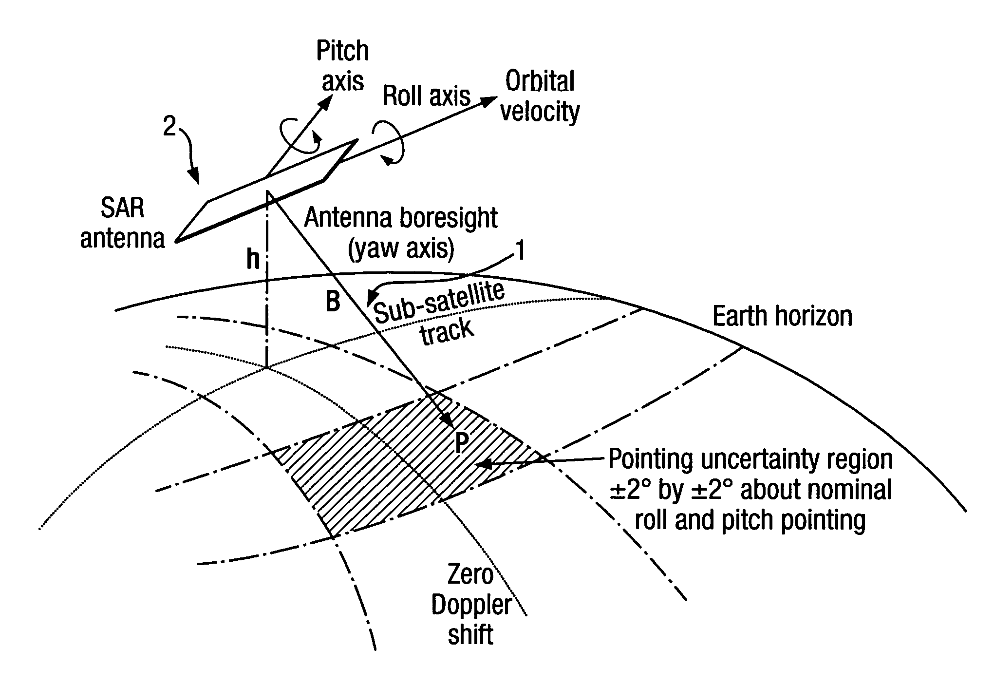
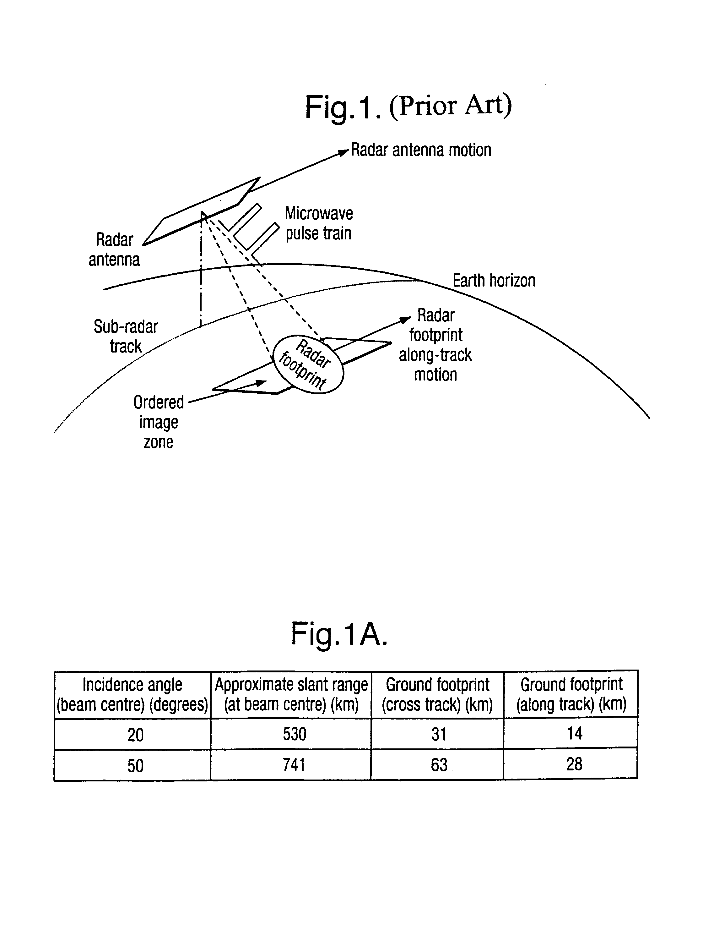
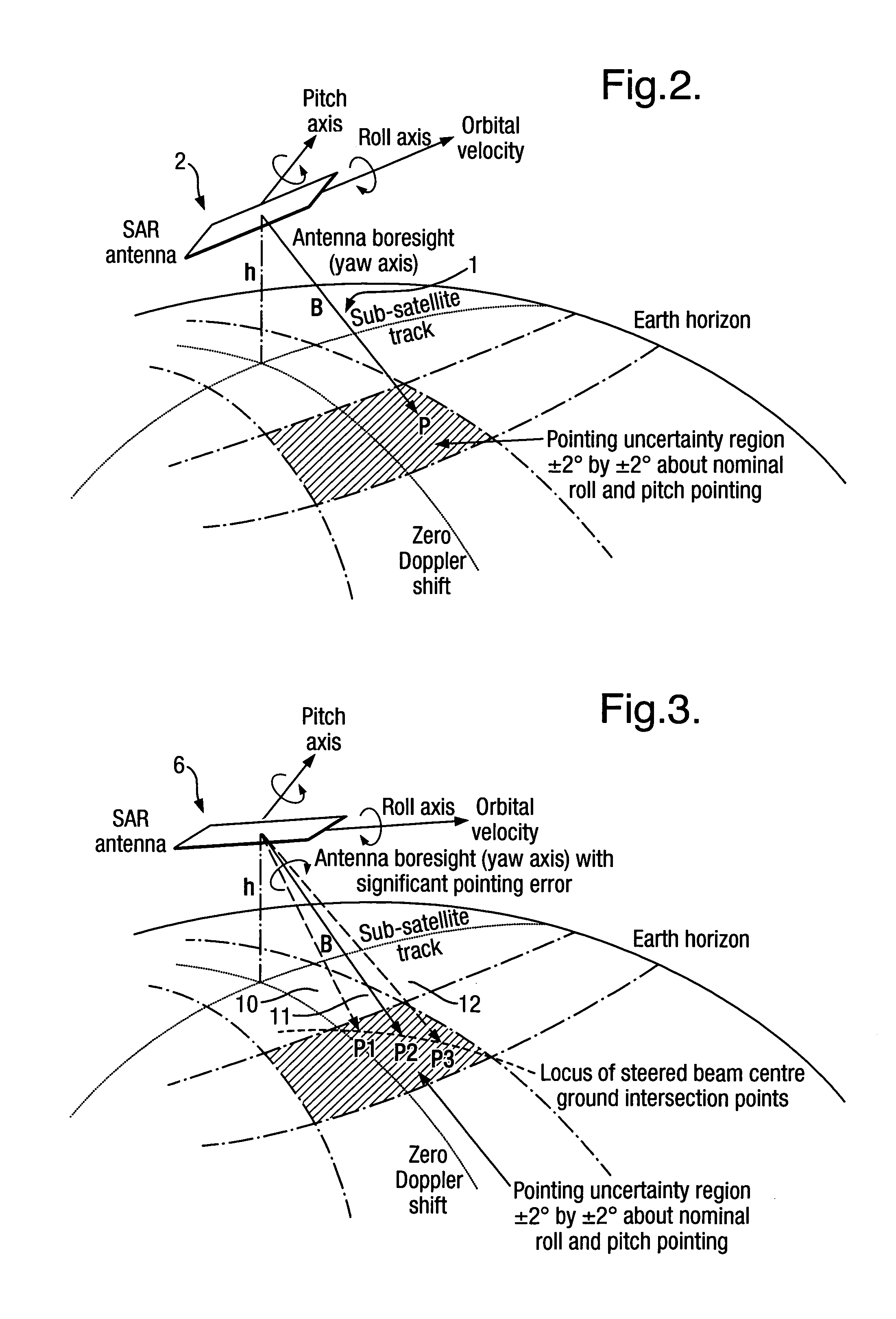
[0046]The inventive attitude sensing technique to be described hereinafter relies for its success upon the acquisition of radar echo data from a selected scattering surface, the surface of the Earth for example. Radar instruments that are particularly suited to providing this type of data may be airborne or space borne, and frequently make use of synthetic aperture processing so as to enhance the spatial resolution on the ground that tee imaging creates. However, whilst the described inventive attitude sensing technique is well-suited to synthetic aperture radar (SAR), it is equally suited to other radar types (for example, forward looking imaging radar and highly squinted imaging radar which look half sideways / half forwards). Accordingly, the term “radar” is used in the description throughout.

[0047]In the following description, there is first provided a summary of the basic assumptions underlying the description of the preferred embodiments of the invention. Thereafter, there is pr...


PUM


Abstract

An imaging apparatus has transmitter illuminating a selected surface with a radar beam footprint, and processor for profiling / processing the radar returns so as to derive attitude information in real time about a number of predefined axes associated with the radar which depends upon the relative dispositions of the radar, the selected surface and upon the radar beam footprint characteristics.A plurality of transmit beams image the surface and the processing arrangement has the capability of determining roll, pitch and / or yaw pointing data associated with the radar, such pointing data being determined by derivation of the attitude information and by selective input of terrain elevation data so as to take account of variations in the radar viewing geometry with terrain elevation.This provides a low cost advantage over known radar designs, and retains utility for many applications, for example spaceborne and airborne applications.

Description

[0001]This application is the U.S. national phase of international application PCT / GB04 / 02208 filed 20 May 2004, which designated the US and claims priority to GB Application No. 0311646.4, filed 21 May 2003 and EP Application No. 03253158.4, filed 21 May 2003. The entire contents of these applications are incorporated herein by reference.FIELD OF THE INVENTION[0002]This invention concerns improvements relating to an imaging apparatus and method. More particularly, though not exclusively, this invention concerns synthetic aperture imaging apparatus for imaging the Earth's surface from an orbiting satellite and which is used for providing radar attitude information.BACKGROUND OF THE INVENTION[0003]Known Imaging Radar Principles[0004]FIG. 1 shows an example of conventional imaging radar apparatus orbiting the Earth. As shown in the Figure, the imaging radar is an active instrument that illuminates the ground through a narrow beam antenna which is also used to receive the radiation sca...

Claims


Application Information

Patent Timeline
Patent Type & Authority Patents(United States)
IPC IPC(8): G01S13/89G01S13/90G01S13/00G01S7/40
CPCG01S13/90G01S7/4021G01S13/9056G01S13/9054
Inventor HALL, CHARLES DAVIDPRIESTLEY, DAVID MARTIN
Owner ASTRIUM GMBH
Why Eureka
Try Eureka