

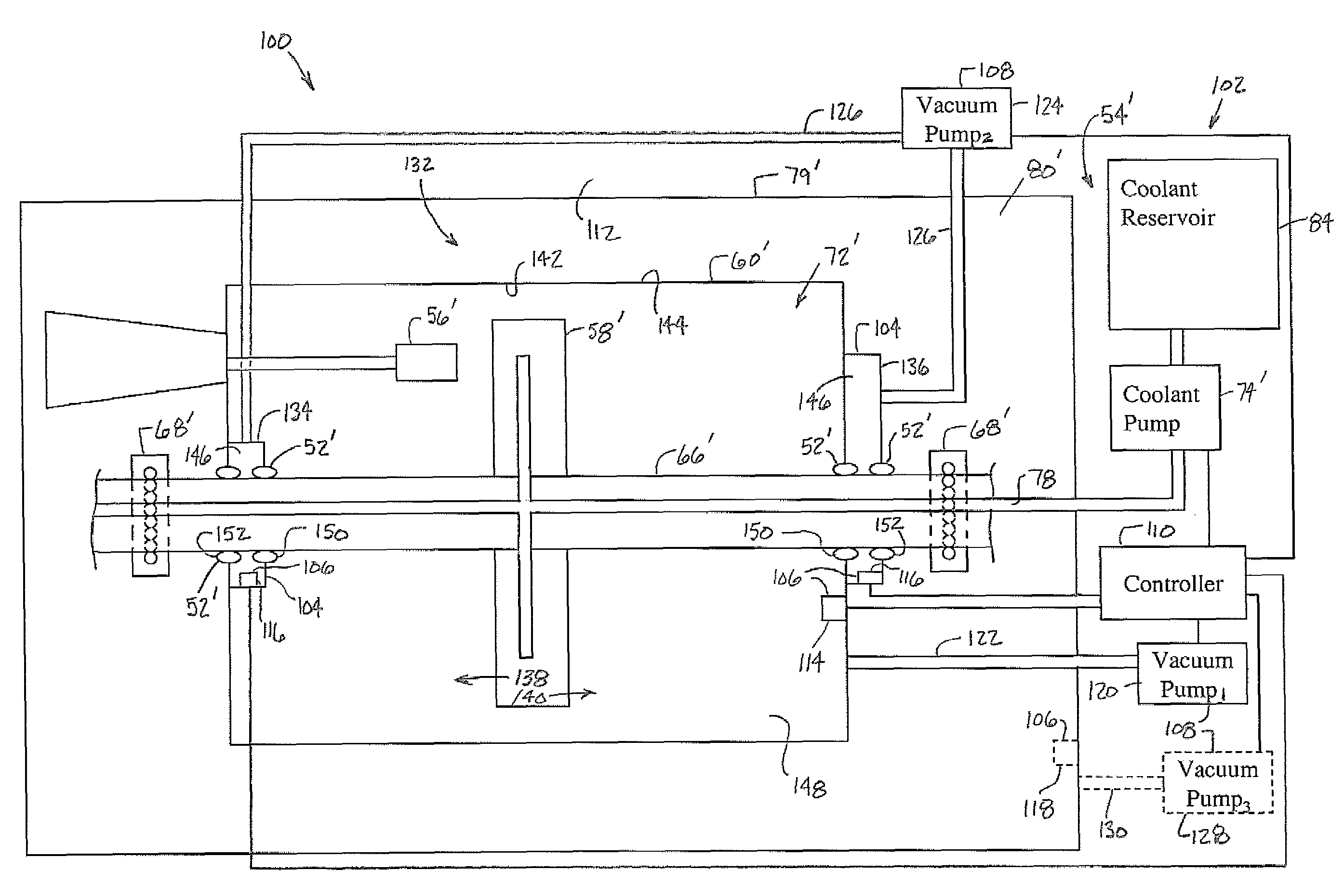
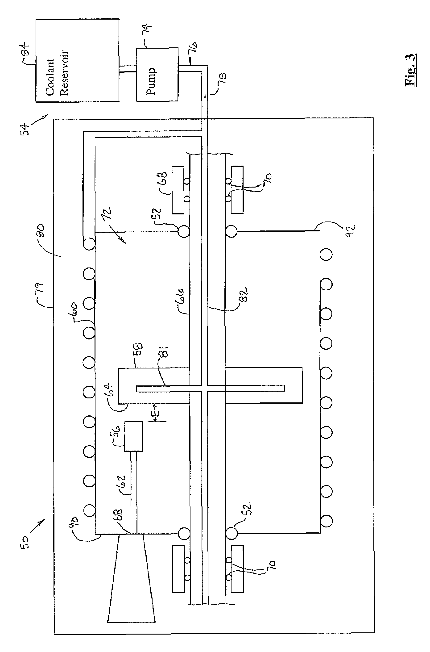
Cantilever and straddle x-ray tube configurations for a rotating anode with vacuum transition chambers
a technology of transition chamber and rotating anode, which is applied in the field of computed tomography (ct) imaging systems, can solve the problems of high voltage instability, inability to utilize grease or oil lubricated bearings, and degradation of high voltage vacuum
- Summary
- Abstract
- Description
- Claims
- Application Information
AI Technical Summary
Benefits of technology
Problems solved by technology
Method used
Image

Examples
Embodiment Construction
[0023]In the following Figures the same reference numerals will be used to refer to the same components. While the present invention is described with respect to a system for sealing and cooling a rotating anode and associated vacuum vessel, the present invention may be adapted and applied to various systems including computed tomography (CT) systems, x-ray systems, Mammography systems, Vascular systems, Surgical-C systems, Radiographic (RAD) systems, RAD and Fluoroscopy Systems, and mixed modalities, such as CT-positron emission tomography (PET) or CT-Nuclear.
[0024]In the following description, various operating parameters and components are described for one constructed embodiment. These specific parameters and components are included as examples and are not meant to be limiting.
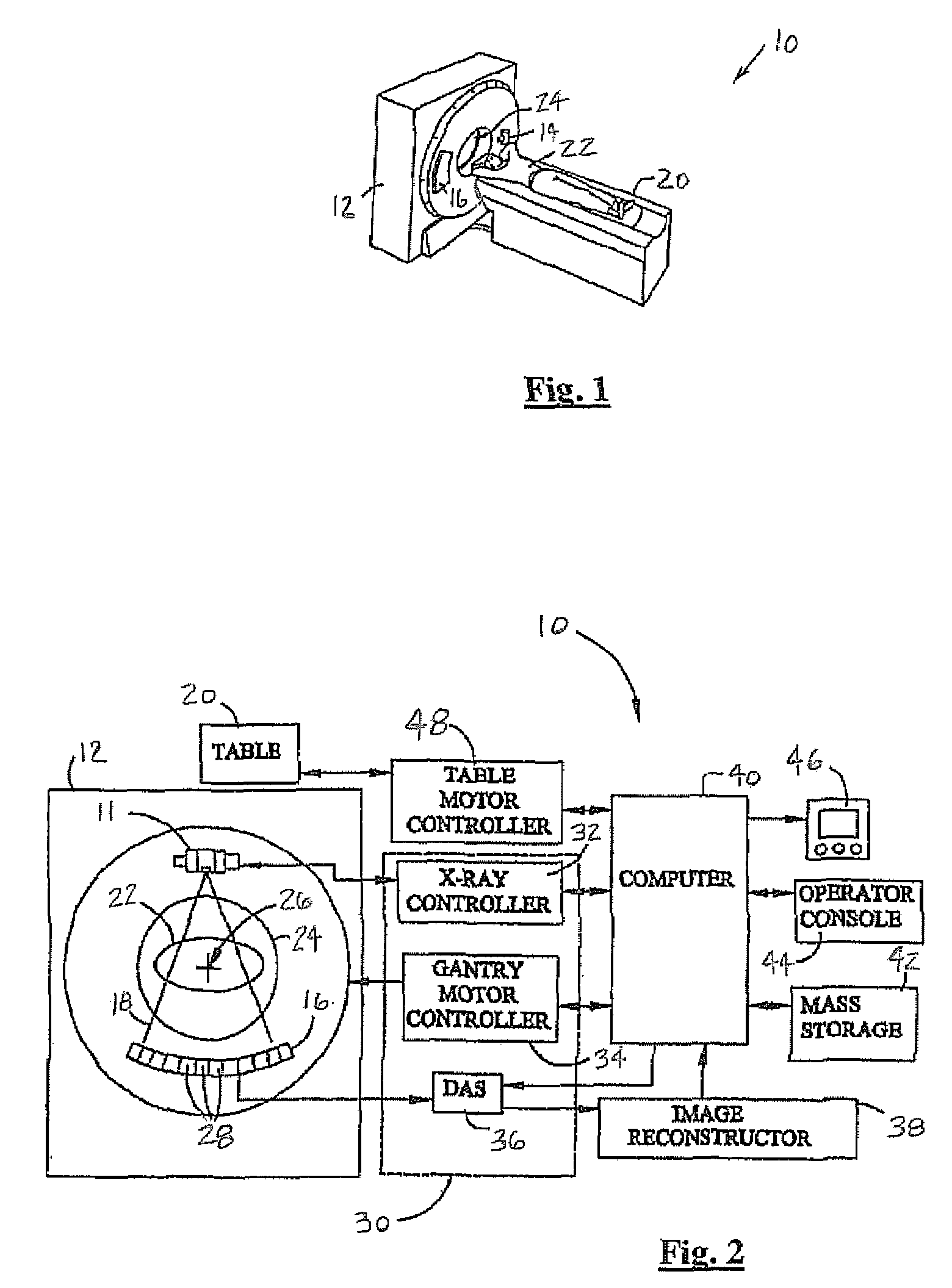
[0025]Referring now to FIGS. 1 and 2, perspective and schematic block diagrammatic views of a CT imaging system 10 incorporating an x-ray source or x-ray tube assembly 11 are shown in accordance with an em...
PUM
 Abstract
Description
Claims
Application Information